M955 Accelerometer not found on specified port
-
Duet 3
RepRapFirmware version: 3.4.4
Duet Web Control v3
Printer architecture: CartesianProblem: I am trying to connect the LIS3DH accelerometer to the Duet board to utilize the input shaping functionality, but after wiring the LIS3DH to the Duet board, the Duet board does not recognize any accelerometer being connected. I made sure to follow the wiring schematics in the documentation. An error pops up regarding the M955 command, saying that an accelerometer could not be found on the specified port.
Below is the config.g code
G90                                              ; send absolute coordinates...
M83                                              ; ...but relative extruder moves
M550 P"Duet 3"                                   ; set printer name

; Drives
M569 P0.0 S0 D3                                   ; physical drive 0.0 goes backward (Edited 10/10/22 by AXL)
;M569.7 P0.0 C"out3"                              ; For operating the Z axis brake TESTING NOT SUPPORTED ON MAIN BOARD, NEED SINGLE STEPPER DRIVER EXPANSION BOARD 10/6/2022 AXL
M569 P0.1 S0 D3                                   ; physical drive 0.1 goes backward (Edited 10/10/22 by AXL)
M569 P0.2 S0                                     ; physical drive 0.2 goes backward (Edited 10/10/22 by AXL)
M569 P0.3 S0                                     ; physical drive 0.3 goes backward (Edited 10/10/22 by AXL)
M569 P0.4 S0                                     ; physical drive 0.4 goes backward
M584 X0.0 Y0.1 Z0.2 E0.3:0.4                     ; set drive mapping
M350 X16 Y16 Z16 E16:16 I1                       ; configure microstepping with interpolation
M92 X640.00 Y640.00 Z640.00 E837.20:837.20       ; set steps per mm
M566 X450.00 Y450.00 Z900.00 E120.00:120.00      ; set maximum instantaneous speed changes (mm/min)
M203 X3000.00 Y3000.00 Z3000.00 E1200.00:1200.00 ; set maximum speeds (mm/min)
M201 X300.00 Y300.00 Z300.00 E100.00:100.00      ; set accelerations (mm/s^2)
M906 X2000 Y2000 Z2000 E800:800 I30              ; set motor currents (mA) and motor idle factor in per cent
M84 S30                                          ; Set idle timeout

; Axis Limits
M208 X-125 Y-125 Z0 S1                                 ; set axis minima
M208 X125 Y125 Z100 S0                           ; set axis maxima

; Endstops
M574 X1 S1 P"io0.in"                             ; configure switch-type (e.g. microswitch) endstop for low end on X via pin io0.in
M574 Y1 S1 P"io1.in"                             ; configure switch-type (e.g. microswitch) endstop for low end on Y via pin io1.in
M574 Z2 S1 P"io2.in"                             ; configure switch-type (e.g. microswitch) endstop for high end on Z via pin io2.in

; Z-Probe
M558 P0 H5 F120 T6000                            ; disable Z probe but set dive height, probe speed and travel speed
M557 X15:215 Y15:195 S20                         ; define mesh grid

; Heaters
M308 S0 P"temp0" Y"thermistor" T120000 B4800     ; configure sensor 0 as thermistor on pin temp0
M950 H0 C"out0" T0                               ; create bed heater output on out0 and map it to sensor 0
M307 H0 R0.267 K0.258:0.000 D16.77 E1.35 S1.00 B0; enable PID mode for the bed heater and set PWM limit Tuned in bang-bang mode 10/17/2022 by AXL
M140 H0                                          ; map heated bed to heater 0
M143 H0 S120                                     ; set temperature limit for heater 0 to 120C
M308 S1 P"temp1" Y"thermistor" T120000 B4800     ; configure sensor 1 as thermistor on pin temp1
M950 H1 C"out1" T1                               ; create nozzle heater output on out1 and map it to sensor 1
M307 H1 R1.583 K0.257:0.067 D6.88 E1.35 S1.00 B0 ; Tuned in PID mode 10/6/2022 by AXL
M307 H1 B0 S1.00                                 ; disable bang-bang mode for heater  and set PWM limit
M143 H1 S280                                     ; set temperature limit for heater 1 to 280C
M308 S2 P"temp2" Y"thermistor" T120000 B4800     ; configure sensor 2 as thermistor on pin temp2
M950 H2 C"out2" T2                               ; create nozzle heater output on out2 and map it to sensor 2
M307 H2 R1.612 K0.250:0.070 D6.58 E1.35 S1.00 B0 ; Tuned in PID mode 10/6/2022 by AXL
M307 H2 B0 S1.00                                 ; disable bang-bang mode for heater  and set PWM limit
M143 H2 S280                                     ; set temperature limit for heater 2 to 280C

; Fans
M950 F0 C"out8" Q500                             ; create fan 0 on pin out8 and set its frequency
M106 P0 S0 H-1                                   ; set fan 0 value. Thermostatic control is turned off
M950 F1 C"out9" Q500                             ; create fan 1 on pin out9 and set its frequency
M106 P1 S0 H-1                                   ; set fan 1 value. Thermostatic control is turned off

; Tools
M563 P0 S"TPU" D0 H1 F0                          ; define tool 0
G10 P0 X0 Y0 Z0                                  ; set tool 0 axis offsets
G10 P0 R0 S0                                     ; set initial tool 0 active and standby temperatures to 0C
M563 P1 S"PLA" D1 H2 F1                          ; define tool 1
G10 P1 X0 Y0 Z0                                  ; set tool 1 axis offsets
G10 P1 R0 S0                                     ; set initial tool 1 active and standby temperatures to 0C


;DIW Output
M950 P0 C"io3.out" Q2							 ; Attempt at DIW foot Pedal Control 10/17/2022 AXL
M950 P2 C"out7" Q0								 ; sets solenoid valve as Out 7

;Brake Output
M950 P1 C"out3" Q0

;Accelerometer
M955 P0 I5 C"spi.cs3+spi.cs2"
Here is where the wires are connected on the Duet board
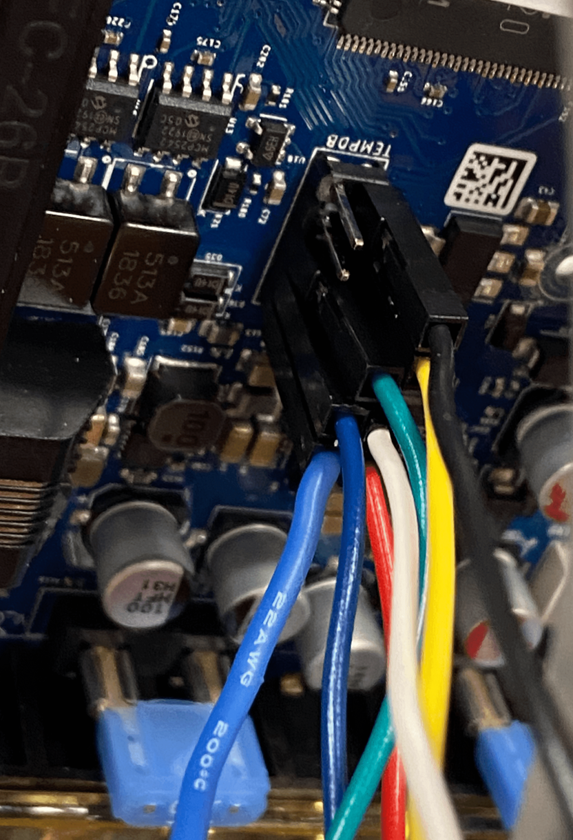
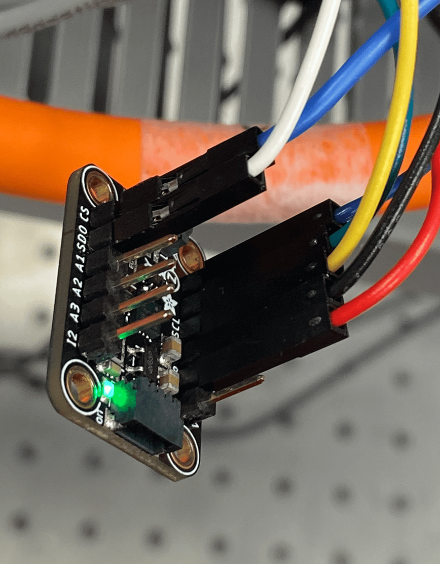
Here are the wires on the accelerometer side
Thank you for your time
-
How long is the cabling? People have had best luck using a USB3 cable.
-
The length of the cables that were used in the picture were around 5 inches long. I'll try the USB3 cable approach and see how that goes.
-
@BryanPlummer I would expect it to work with cables that short. I will study your wiring photos.
-
@BryanPlummer it's a little hard to tell from your photo, but I think you have the red and white wires plugged into the wrong pins on the Duet. They should go to pins 8 and 6 respectively, but I think you have connected them to pins 10 and 8.