DUET 3D MAINBOARD 6HC WIRING
-
Hi,
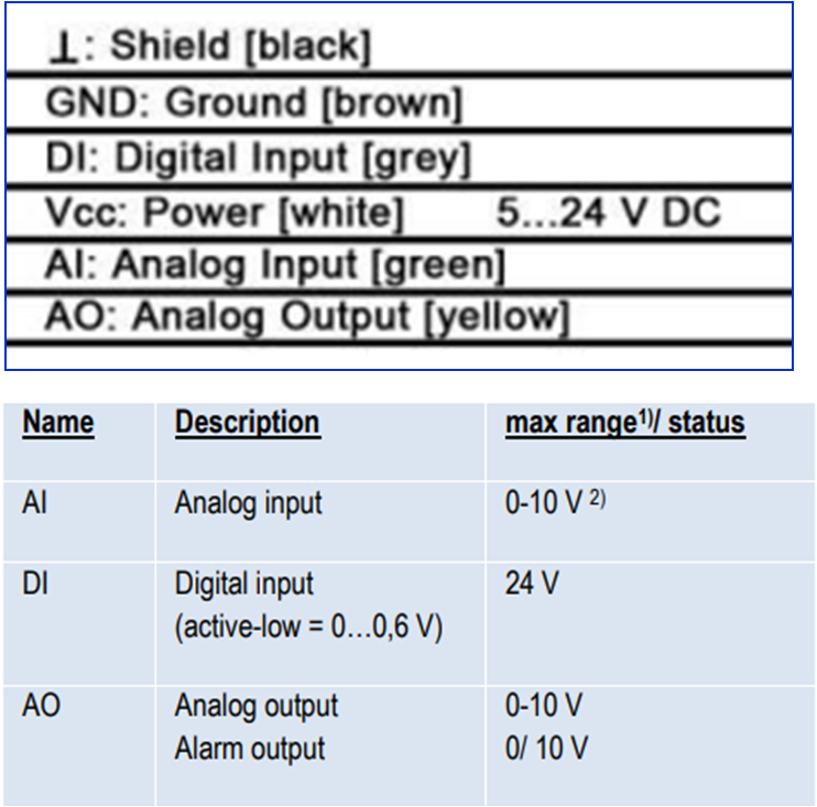
I am trying to connect a thermal imaging camera to Duet 3D Mainboard 6HC. The camera has has 5 wires (picture of the same is attached below for reference). Requesting your feedback for the following queriesQuery 1) The Power Supply requires 24VDC, would the two options mentioned below suffice the power supply requirement?
Option 1 : Connecting the GND Cable (brown color) and VCC Cable (white color) to the OUT 0 which has 12 ~ 36VDC? [By doing so I may be supplying more voltage than required, would it damage the electronics of the camera]
Option 2 : Connecting GND and VCC cables directly to Power supply unit (LRS-350-24) of the -VE and +VE terminal Pins?Query 2) The other three wires are the 1 Digital Input Wire, requiring 24VDC (Grey Color) and 1 Analog Output Wire, requiring 0~10 VDC (Yellow Color) and 1 Shield Wire (Black Color).
2a) Which port on the Duet 3D Mainboard 6HC has a such a configuration DI(24VDC) and AO(10VVDC) and a ground?
2b) What are the G-Codes to config. the DI and AO signals?
-
@SANJR
This looks similar (but is obviously very different) to controlling a spindle from a digital converter, but I would suggest the power supply to the camera be taken directly from the PSU's 24V supply and leaving the digital control side to the control board. If you'd prefer to control the supply voltage to the camera, you could use a relay, like this.I'm assuming, of course, you're using a 24V PSU?
You'd definitely need to check it would work the same way as a digital controlled milling motor, but if you look here, that might give you a starting point?
Good luck.
-
@Nightowl Thanks. I would be connecting the power supply directly from the PSU.
Regarding the Digital Input and Analog output to which shall I connect?
Because the DI required an 24V and AO requires an 10V
Requesting help from u guys