What could have caused this kind of damage to my Duet3 6HC?
-
Happy new year to you all! I sincerely which you all good health and lots of luck.
My year ended with a bang. I was about to finish making a part on my CNC-Lathe conversion, which has been working flawless so far.
If I recall correctly, I just turned on the spindle and POFF! The board is burned between the Network connector housing and the io4 connector.


I did not find any obvious shorts in my wiring or any metallic object that could have caused a short on the board. The underside of the PCB looks fine.
The controller has a 10A AC Fuse that got triggered, so I recon there must have been some serious current involved.
-
@MaxGyver I'm sorry to hear that your board has been damaged. What was connected to the IO4 connector, and what board version is the Duet 6HC?
Duet WiFi hardware designer and firmware engineer
Please do not ask me for Duet support via PM or email, use the forum
http://www.escher3d.com, https://miscsolutions.wordpress.com -
@dc42 said in What could have caused this kind of damage to my Duet3 6HC?:
@MaxGyver I'm sorry to hear that your board has been damaged. What was connected to the IO4 connector, and what board version is the Duet 6HC?
Here my list of io connections:
- io1 -> Indctive Endstop (5V)
- io2 -> Inductive Endstop (5V)
- io4 -> Spindle Cover Switch
- io3 -> Emergency stop switch
- io5 -> Z-Probe
The Board version is v1.01
I have a hunch that the PWM to analog converter is the culprit. I assumed that the input and output pins of the converter have a galvanic separation. If there is no such thing, there could have been an AC voltage potential of approx. 125 V between the converter output and the grounding from the spindle VFD. The fact that the damage is closest to the Ethernet plug also indicates that there has been a short to GND/Shield. The question is why it worked for quite some time before blowing up, and how to avoid this in the future. Presently, the Spindle VFD and rest of the controller have the same grounding. Maybe it is better to have a separate power input for the Spindle controller and just run a signal wire from the Duet to the Lathe for switching the spindle AN/OFF relay and spindle speed signal?
-
@MaxGyver there are two common types of PWM to analog converter, one has isolation and the other doesn't because it has a design fault. See https://docs.duet3d.com/en/User_manual/Machine_configuration/Configuration_CNC#connecting-a-spindle.
Duet WiFi hardware designer and firmware engineer
Please do not ask me for Duet support via PM or email, use the forum
http://www.escher3d.com, https://miscsolutions.wordpress.com -
PS here is the layout of that part of the PCB:
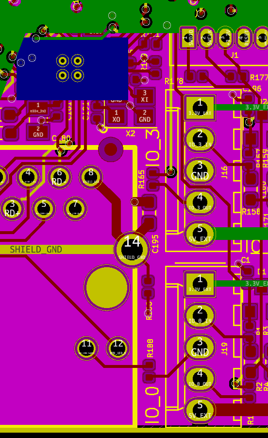
The components between the Ethernet connector and IO_3 are C195 and R165. Does one of them look more badly damaged than the other?
How is the Emergency Stop switch connected?
-
@dc42 said in What could have caused this kind of damage to my Duet3 6HC?:
@MaxGyver there are two common types of PWM to analog converter, one has isolation and the other doesn't because it has a design fault. See https://docs.duet3d.com/en/User_manual/Machine_configuration/Configuration_CNC#connecting-a-spindle.
I used the green type. But since they are all made in China and sold over Amazon, I would not vouch for the quality. Unfortunately, I did not find a suitable alternative.
@dc42 said in What could have caused this kind of damage to my Duet3 6HC?:
The components between the Ethernet connector and IO_3 are C195 and R165. Does one of them look more badly damaged than the other?
How is the Emergency Stop switch connected?It is really hard to see the origin of the damage. I would say R165 is more damaged, but it looks like the origin of the arc was between R165 and C195.
I just checked my wiring again, IO3 was not connected to anything on the other side yet. I was planning to set IO3 as a trigger to stop the nc program if the emergency stop is pressed.
-
@MaxGyver if you were using shielded Ethernet cable, and the shield somehow got connected to AC mains voltage, then C195 could have failed; or possibly there could have been an arc between the Ethernet connector shield and the ground end of C195.
Duet WiFi hardware designer and firmware engineer
Please do not ask me for Duet support via PM or email, use the forum
http://www.escher3d.com, https://miscsolutions.wordpress.com -
The shield was connected to the common grounding of the controller box, if there were an AC voltage potential between the converter output and the common grounding, this could have caused the arc. But this would mean that there is either an AC short or the PWM to voltage converter has no proper galvanic isolation.
I will take some measurements when I get back to the office. Thank you for your support!
-
I have checked the wiring again and found that there is indeed an AC-Voltage between grounding and the 0-10V input of the VFD. I also have to revise my statement about what was connected to Io3 and Io4. Io4 was the CNC-Pendant and Io3 was connected the emergency stop switch in my CNC-Pendant. I disassembled the pendant, but did not find any burned areas or obvious shorts.
Comparing the burned board to a spare one, I noticed that R165 is completely gone.
But I do not understand how the Voltage traversed through the PWM to voltage converter and through the duet to arc over at the Ethernet shield.
The PWM-converter is powered from the same 24V PSU as the duet and connected to out1 on the duet for the PWM Signal (24V)
-
@MaxGyver said in What could have caused this kind of damage to my Duet3 6HC?:
The PWM-converter is powered from the same 24V PSU as the duet and connected to out1 on the duet for the PWM Signal (24V)
Powering the converter from the same 24V supply as the Duet means that the isolation in the converter was lost, because the 0-10V output ground side is almost certainly common with the 24V input. So perhaps the Duet ground was at AC mains voltage, and the Ethernet shield was at ground potential. The voltage rating of R165 may have been exceeded.
Coincidentally, when we did the design review for the version 1.02 board we increased the voltage rating of R165 and the capacitor, and changed the layout to handle higher voltages between the Ethernet shield and ground. However, we did this to guard against static discharge rather than because there might be a high voltage continuously between those points under normal conditions.