adjus manual speed of the fan
-
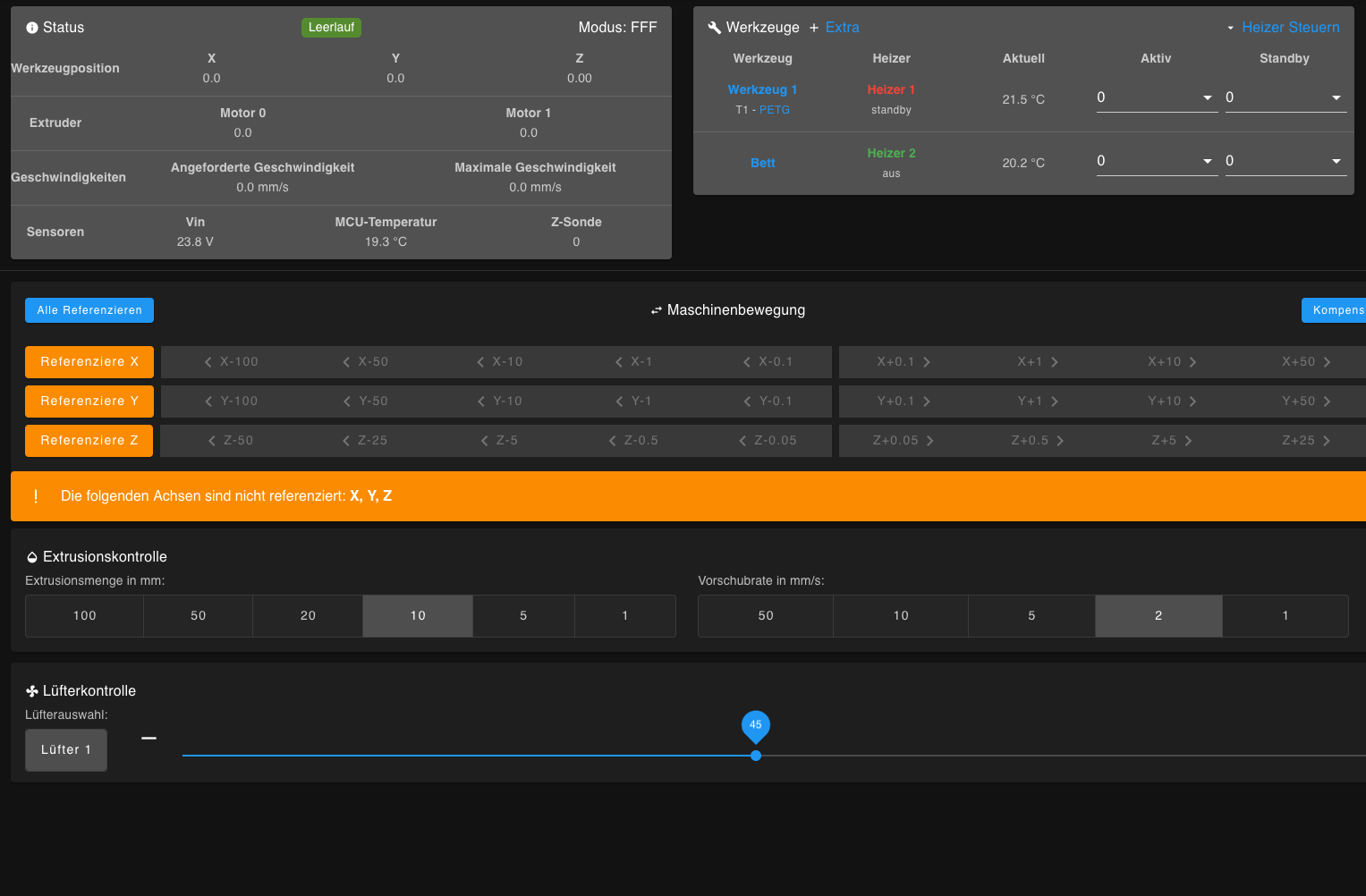
Suddenly the manual speed of the fan can no longer be adjusted.. The fan only runs at a constant speed
 Bildschirmfoto 2022-12-20 um 16.39.04
Here the code...i did´t change anything:
; Fans
;M950 F0 C"fan0" Q500 ; create fan 0 on pin fan0 and set its frequency
;M106 P0 S1 H0 T45 ; set fan 0 value. Thermostatic control is turned on
M950 F1 C"fan1" Q500 ; create fan 1 on pin fan1 and set its frequency
;M106 P1 S1 H1 T45 ; set fan 1 value. Thermostatic control is turned on -
@axiom you only seem to have an M950 there. You need an M106 command as well. Best to post your full config rather than just a snippet
-
@jay_s_uk Hello, the command was actually commented out, but activating it didn't change anything.
The error message comes:
M106 Pundefinded S0.52 Error: M106: expected mother after "P"
Here is a screenshot:
and here is the complete code as requested:Configuration file for Duet WiFi (firmware version 3.3)
; executed by the firmware on start-up
;
; generated by RepRapFirmware Configuration Tool v3.3.12 on Wed Aug 24 2022 12:56:11 GMT+0200 (Mitteleuropäische Sommerzeit); General preferences
M575 P1 S1 B57600 ; enable support for PanelDue
G90 ; send absolute coordinates...
M83 ; ...but relative extruder moves
M550 P"DUKA1300" ; set printer name; Network
M552 S1 ; enable network
M586 P0 S1 ; enable HTTP
M586 P1 S0 ; disable FTP
M586 P2 S0 ; disable Telnet; Drives
M569 P1 S1 ; physical drive 0 goes forwards
M569 P1 S1 ; physical drive 1 goes forwards
M569 P2 S0 ; physical drive 2 goes forwards
M569 P3 S0 ; physical drive 3 goes forwards extruder1
M569 P4 S1 ; physical drive 4 goes forwards
M584 X0 Y1 Z2 E3:4 ; set drive mapping
M350 X16 Y16 Z16 E16:16 I1 ; configure microstepping with interpolation
;M92 X80.00 Y80.00 Z400.00 E420.00:420.00 ; set steps per mm
M92 X80.00 Y80.00 Z640.00 E320.20:320.51 ; set steps per mm
M566 X900.00 Y900.00 Z100.00 E120.00:120.00 ; set maximum instantaneous speed changes (mm/min)
M203 X6000.00 Y6000.00 Z1000.00 E1200.00:1200.00 ; set maximum speeds (mm/min)
M201 X500.00 Y500.00 Z40.00 E250.00:250.00 ; set accelerations (mm/s^2)
M906 X1800 Y1800 Z2400 E1800:1800 I30 ; set motor currents (mA) and motor idle factor in per cent
M84 S30 ; Set idle timeout; Axis Limits
M208 X50 Y115 Z0 S1 ; set axis minima
M208 X628 Y845 Z1200 S0 ; set axis maxima; Endstops
M574 X1 S1 P"xstop" ; configure switch-type (e.g. microswitch) endstop for low end on X via pin xstop
M574 Y1 S1 P"ystop" ; configure switch-type (e.g. microswitch) endstop for low end on Y via pin ystop
;M574 Z2 S1 P"zstop" ; configure switch-type (e.g. microswitch) endstop for high end on Z via pin zstop
;M574 Z2 S2 ; configure Z-probe endstop for high end on Z
; Z-Probe
M558 P1 C"!zprobe.in" H5 F120 T6000 ; set Z probe type to unmodulated and the dive height + speeds
G31 P1000 X-20 Y80 Z0.492 ; set Z probe trigger value, offset and trigger height
M557 X50:600Y115:800S100 ; define mesh grid; Heaters
M308 S0 P"e1temp" Y"thermistor" T100000 B4138 ; configure sensor 0 as thermistor on pin e1temp
M950 H0 C"e1heat" T0 ; create nozzle heater output on e1heat and map it to sensor 0
M307 H0 R1.797 K0.742:0.000 D7.57 E1.35 S1.00 B0 V23.8 ; disable bang-bang mode for heater and set PWM limit
M143 H0 S250 ; set temperature limit for heater 0 to 250C
M308 S1 P"e0temp" Y"thermistor" T100000 B4138 ; configure sensor 1 as thermistor on pin e0temp
M950 H1 C"e0heat" T1 ; create nozzle heater output on e0heat and map it to sensor 1
M307 H1 R1.797 K0.742:0.000 D7.57 E1.35 S1.00 B0 V23.8 ; disable bang-bang mode for heater and set PWM limit
M143 H1 S250 ; set temperature limit for heater 1 to 250C
M308 S2 P"bedtemp" Y"thermistor" T100000 B4138 ; configure sensor 2 as thermistor on pin bedtemp
M950 H2 C"bedheat" T2 ; create bed heater output on bedheat and map it to sensor 2
M307 H2 R0.283 K0.463:0.000 D7.17 E1.35 S1.00 B0 ; enable bang-bang mode for the bed heater and set PWM limit
M140 H2 ; map heated bed to heater 2
M143 H2 S280 ; set temperature limit for heater 2 to 280C; Fans
;M950 F0 C"fan0" Q500 ; create fan 0 on pin fan0 and set its frequency
;M106 P0 S1 H0 T45 ; set fan 0 value. Thermostatic control is turned on
M950 F1 C"fan1" Q500 ; create fan 1 on pin fan1 and set its frequency
M106 P1 S1 H1 T45 ; set fan 1 value. Thermostatic control is turned on; Tools
;M563 P0 D0 H0 F0 ; define tool 0
;G10 P0 X0 Y0 Z0 ; set tool 0 axis offsets
;G10 P0 R0 S0 ; set initial tool 0 active and standby temperatures to 0C
M563 P1 D1 H1 F1 ; define tool 1
G10 P1 X45 Y45 Z0 ; set tool 1 axis offsets
G10 P1 R0 S0 ; set initial tool 1 active and standby temperatures to 0C; Custom settings are not defined
; Miscellaneous
M911 S10 R11 P"M913 X0 Y0 G91 M83 G1 Z3 E-5 F1000" ; set voltage thresholds and actions to run on power loss -
@axiom so a couple of things about your config.
You only have a hotend cooling fan defined so that will automatically come on once the hotend reaches 45 degrees and will run at a constant speed and won't be controllable thought DWC.You have the config for your part cooling fan commented out so it won't function. This also results in you have no part cooling fan mapped to your tool (your commented out part cooling fan is F0 and that's what you have mapped to the tool), resulting in the errors you see when the gcode tries to change it, as it doesn't exist.
-
@jay_s_uk
I do not understand that completely. I don't want to activate Tool 0 and Fan 0, it's just about Tool1 and Fan 1.
I also commented out the M106 command and the controller in the DWC is visible and active.here is also no more error message. But the fan is already running when you start it... could it be a hardware problem?
; Configuration file for Duet WiFi (firmware version 3.3)
; executed by the firmware on start-up
;
; generated by RepRapFirmware Configuration Tool v3.3.12 on Wed Aug 24 2022 12:56:11 GMT+0200 (Mitteleuropäische Sommerzeit); General preferences
M575 P1 S1 B57600 ; enable support for PanelDue
G90 ; send absolute coordinates...
M83 ; ...but relative extruder moves
M550 P"DUKA1300" ; set printer name; Network
M552 S1 ; enable network
M586 P0 S1 ; enable HTTP
M586 P1 S0 ; disable FTP
M586 P2 S0 ; disable Telnet; Drives
M569 P1 S1 ; physical drive 0 goes forwards
M569 P1 S1 ; physical drive 1 goes forwards
M569 P2 S0 ; physical drive 2 goes forwards
M569 P3 S0 ; physical drive 3 goes forwards extruder1
M569 P4 S1 ; physical drive 4 goes forwards
M584 X0 Y1 Z2 E3:4 ; set drive mapping
M350 X16 Y16 Z16 E16:16 I1 ; configure microstepping with interpolation
;M92 X80.00 Y80.00 Z400.00 E420.00:420.00 ; set steps per mm
M92 X80.00 Y80.00 Z640.00 E320.20:320.51 ; set steps per mm
M566 X900.00 Y900.00 Z100.00 E120.00:120.00 ; set maximum instantaneous speed changes (mm/min)
M203 X6000.00 Y6000.00 Z1000.00 E1200.00:1200.00 ; set maximum speeds (mm/min)
M201 X500.00 Y500.00 Z40.00 E250.00:250.00 ; set accelerations (mm/s^2)
M906 X1800 Y1800 Z2400 E1800:1800 I30 ; set motor currents (mA) and motor idle factor in per cent
M84 S30 ; Set idle timeout; Axis Limits
M208 X50 Y115 Z0 S1 ; set axis minima
M208 X628 Y845 Z1200 S0 ; set axis maxima; Endstops
M574 X1 S1 P"xstop" ; configure switch-type (e.g. microswitch) endstop for low end on X via pin xstop
M574 Y1 S1 P"ystop" ; configure switch-type (e.g. microswitch) endstop for low end on Y via pin ystop
;M574 Z2 S1 P"zstop" ; configure switch-type (e.g. microswitch) endstop for high end on Z via pin zstop
;M574 Z2 S2 ; configure Z-probe endstop for high end on Z
; Z-Probe
M558 P1 C"!zprobe.in" H5 F120 T6000 ; set Z probe type to unmodulated and the dive height + speeds
G31 P1000 X-20 Y80 Z2.71 ; set Z probe trigger value, offset and trigger height
M557 X50:600Y115:800S100 ; define mesh grid; Heaters
M308 S0 P"e1temp" Y"thermistor" T100000 B4138 ; configure sensor 0 as thermistor on pin e1temp
M950 H0 C"e1heat" T0 ; create nozzle heater output on e1heat and map it to sensor 0
M307 H0 R1.797 K0.742:0.000 D7.57 E1.35 S1.00 B0 V23.8 ; disable bang-bang mode for heater and set PWM limit
M143 H0 S250 ; set temperature limit for heater 0 to 250C
M308 S1 P"e0temp" Y"thermistor" T100000 B4138 ; configure sensor 1 as thermistor on pin e0temp
M950 H1 C"e0heat" T1 ; create nozzle heater output on e0heat and map it to sensor 1
M307 H1 R1.797 K0.742:0.000 D7.57 E1.35 S1.00 B0 V23.8 ; disable bang-bang mode for heater and set PWM limit
M143 H1 S250 ; set temperature limit for heater 1 to 250C
M308 S2 P"bedtemp" Y"thermistor" T100000 B4138 ; configure sensor 2 as thermistor on pin bedtemp
M950 H2 C"bedheat" T2 ; create bed heater output on bedheat and map it to sensor 2
M307 H2 R0.283 K0.463:0.000 D7.17 E1.35 S1.00 B0 ; enable bang-bang mode for the bed heater and set PWM limit
M140 H2 ; map heated bed to heater 2
M143 H2 S280 ; set temperature limit for heater 2 to 280C; Fans
;M950 F0 C"fan0" Q500 ; create fan 0 on pin fan0 and set its frequency
;M106 P0 S1 H0 T45 ; set fan 0 value. Thermostatic control is turned on
M950 F1 C"fan1" Q500 ; create fan 1 on pin fan1 and set its frequency
;M106 P1 S1 H1 T45 ; set fan 1 value. Thermostatic control is turned on; Tools
;M563 P0 D0 H0 F0 ; define tool 0
;G10 P0 X0 Y0 Z0 ; set tool 0 axis offsets
;G10 P0 R0 S0 ; set initial tool 0 active and standby temperatures to 0C
M563 P1 D1 H1 F1 ; define tool 1
G10 P1 X45 Y45 Z0 ; set tool 1 axis offsets
G10 P1 R0 S0 ; set initial tool 1 active and standby temperatures to 0C; Custom settings are not defined
; Miscellaneous
M911 S10 R11 P"M913 X0 Y0 G91 M83 G1 Z3 E-5 F1000" ; set voltage thresholds and actions to run on power lossBildschirmfoto 2023-01-07 um 11.48.17
-
@axiom even if I comment out all fans, the fan doesn't work...on the other pins..I plugged it into fan1
-
@axiom I have now rewritten everything to fan 0 and it works....what can be broken on the board...can I fix it?
; Fans
M950 F0 C"fan0" Q500 ; create fan 0 on pin fan0 and set its frequency
;M106 P0 S1 H0 T45 ; set fan 0 value. Thermostatic control is turned on
;M950 F1 C"fan1" Q500 ; create fan 1 on pin fan1 and set its frequency
;M106 P1 S1 H1 T45 ; set fan 1 value. Thermostatic control is turned on; Tools
;M563 P0 D0 H0 F0 ; define tool 0
;G10 P0 X0 Y0 Z0 ; set tool 0 axis offsets
;G10 P0 R0 S0 ; set initial tool 0 active and standby temperatures to 0C
M563 P1 D1 H1 F0 ; define tool 1
G10 P1 X45 Y45 Z0 ; set tool 1 axis offsets
G10 P1 R0 S0 ; set initial tool 1 active and standby temperatures to 0C -
@axiom how many fans have you connected to the board, which outputs have you connected them to, and what does each those fans cool?
Duet WiFi hardware designer and firmware engineer
Please do not ask me for Duet support via PM or email, use the forum
http://www.escher3d.com, https://miscsolutions.wordpress.com -
@dc42 Originally I had planned and installed 2 print heads. But for testing only one is active. I have one for the print head (continuous ventilation) and one for the workpiece to regulate).
Everything works too...but unfortunately not on the Fan1 pin...if I adjust it...there is a permanent ventilation. Currently I have changed the sim code and the hardware to Fan0 and everything works... could it be that the Fan1 pin is defective? but how can i fix this? It looks good visually, but I can't look at the back without disassembling everything -
@axiom how long was it working for before you found you could not adjust the speed? Did you change anything?
The Fan1 mosfet could have failed short circuit.
Duet WiFi hardware designer and firmware engineer
Please do not ask me for Duet support via PM or email, use the forum
http://www.escher3d.com, https://miscsolutions.wordpress.com -
@dc42 It worked around 3 months. How coul i fix the shortcut at the fan1 mosfet?
-
Can you grab a photo of the mosfet? Sometimes they appear damaged.
Otherwise you can use a multimeter to check them. Though they are quite small, so you need to be careful with the probe tips.
https://www.youtube.com/watch?v=RkWy1EirEu8
If they are failed, they can be replaced. https://docs.duet3d.com/en/User_manual/Troubleshooting/Parts#fan-mosfet
They typically fail if the fan short circuits either through the wiring or internally to the fan. Does the fan still work when connected directly to voltage?