Duet 3 Mini5+ How to control a 5V optocoupler relay
-
Hi,
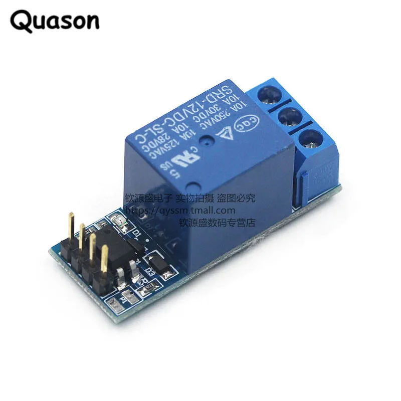
I'm trying to configure one of the Duet 3 Mini5+ GPIO outputs to control a 5V SSR (it has 'YS-1 Realy' printed on the PCB).
I had this working on a Raspberry Pi 3B+ via Octoprint, and was using it control the mains power to an LED power brick for the lighting strip for my 3D printer enclosure.
In my config.g, I've configured io3.out using M950 with:
M950 P0 C"io3.out" ; create LED control signal on io3.outI've wired up the 5V_EXT, GND and io3.out connections of the io_3 jumper to the Vin, GND and CHin inputs of the relay board respectively, and checked the connections with a multimeter. I have 5V between 5V_EXT and GND as I'd expect.
I tried to control the output signal with M42:
M42 P0 S1.0and subsequently,
M42 P0 S0.0Neither of which seem to do anything. Using a multimeter, I seem to see 1V on the io3.out pin relative to GND. I've also tried using M42 P0 S255 as well.
I've also tried using io1 and io4 (and changing the configuration respectively), and also tried enabling the pull-up resistor using M950 P0 C"^io3.out", and inverting the output using M950 P0 C"!io3.out", and also using a different P pin number.
On https://docs.duet3d.com/en/User_manual/Connecting_hardware/IO_GPIO, it states:
- Digital pins (on/off) that can be used to control switches and relays, or read inputs from external switches and triggers.
but how do I use M950 to configure a "digital" output, when it has a default PWM frequency of 500Hz. Is there a specific frequency I should use, e.g. 0 or 65536?
-
@jgrg1
The board switches the negativ side, so you should measure the io3.out against the positive side. -
Back to basics continuity check has revealed that my signal wire has a break in it somewhere. Will swap that out, and try again.
-
That sorted it - and it now works perfectly. Just had to invert the output.
My crimping tool mashed one of the cables, but not the other two. Shonkly cable, I guess.
-
undefined dc42 marked this topic as a question 16 Apr 2023, 16:00
-
undefined dc42 has marked this topic as solved 16 Apr 2023, 16:00