Help Connecting accelerometer to duet2 wifi
-
Hi,
My board is loaded and I could not use the pins in the tutorial. I have paneldue with SD card taking up SPI_MOSI/MISO/SCL pins. So I have used the SPI1 pins instead.
I did the following setup:
Wire# Accelerometer signal Duet signal
1 not connected not connected
2 GND GND
3 not connected not connected
4 SCL SPI1_SCK_BE
5 SDA SPI1_MOSI_B
6 SDO SPI1_MISO
7 INT1 SPI.CS3
8 3V3 +3V3
9 CS SPI.CS4
10 not connected not connectedI have used stranded UTP cable and have added a 250ohm resistor to CS pin.
In my config G I have setup the accelerometer: M955 P0 C"spi.cs4+spi.cs3"
When I run acceleration test I get the following error: Error: M956: Accelerometer not foundHelp me how to do the setup.
-
 undefined Phaedrux marked this topic as a question
-
undefined Phaedrux moved this topic from Tuning and tweaking
-
@daninet You don't connect the accelerometer to the PanelDue connector. You connect it to the Temperature Daughterboard (TEMP_DB) connector. Do you have any temperature daughterboards connected? If not, you can connect the accelerometer directly, and use spi.cs1 and spi.cs2. If you have one temperature daughterboard, connect it the same, but use spi.cs3 and spi.cs4. If you have two temperature daughterboards, you can't connect the accelerometer, as there are no free CS pins.
Ian
Bed-slinger - Mini5+ WiFi/1LC | RRP Fisher v1 - D2 WiFi | Polargraph - D2 WiFi | TronXY X5S - 6HC/Roto | CNC router - 6HC | Tractus3D T1250 - D2 Eth
-
@droftarts
Hi Ian, thank you for your reply.I did reconnect it to the temp daughterboard connector but I have the exact same issue.
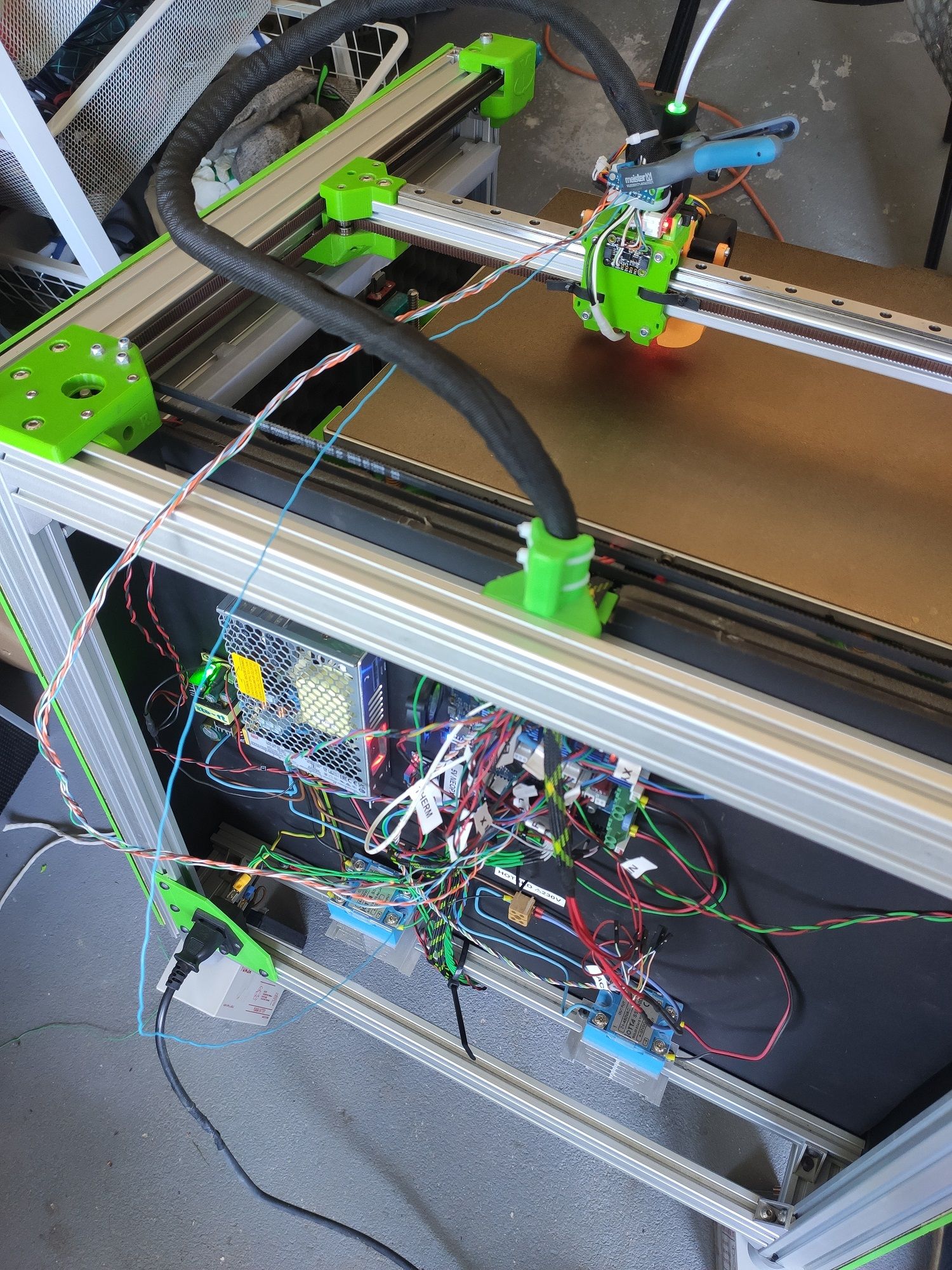
Here is my setup: LIS3DH sensor on the printhead connected with twisted pair ethernet cable
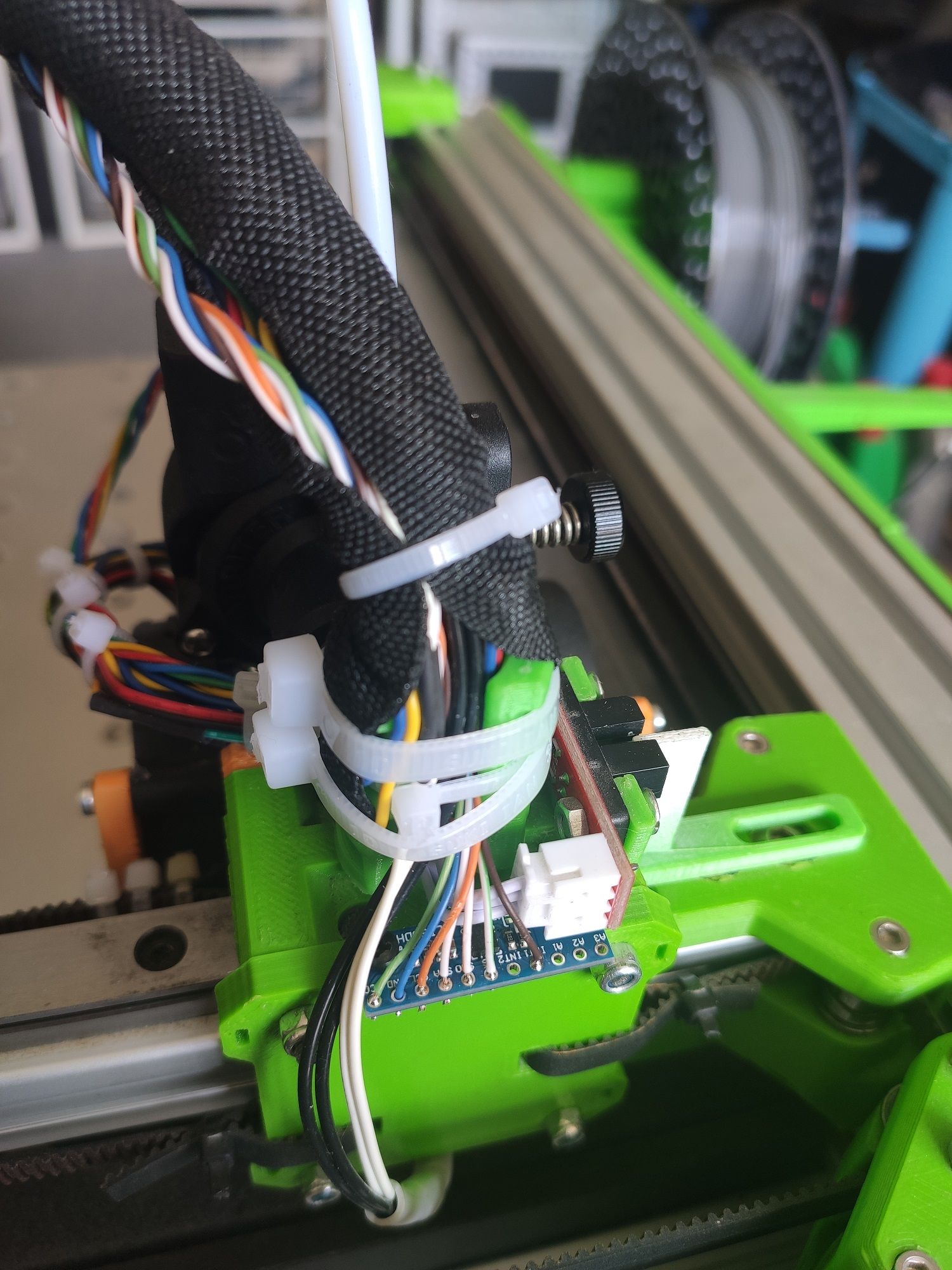
Other end has dupont connectors and now connected to daughterboard pins:

I have checked for cable continuity as well as triple checked the pin layout. It is as per the docs.
In my config G I have setup the accelerometer: M955 P0 C"spi.cs4+spi.cs3"
I have enabled accelerometer plugin in the web interface.
When I run acceleration test (G1 X-50 G4 S2 G1 X50 F20000 M400 M956 P0 S1000 A0) the head moves 50mm to the positive direction then I get the following error: Error: M956: Accelerometer not found -
@daninet It's a little hard to tell what pins the wires are on on the Duet, but if the green 3.3V wire is on pin 8 (top row, second from right), rather than pin 10 (top row, furthest right), the rest looks correct. Your configuration also looks correct. Maybe the CS wire (white with green stripe) is too close to other wires? We say:
We have found that one reason for this is that transitions on SDO are capacitively coupled into CS in the cable, especially if these signals use adjacent conductors. This causes a glitch on CS of a few nanoseconds, which is sufficient to cause the accelerometer to stop transmitting. This is why we recommend that you keep th CS signal away from other signal wires. Where this has not been done and the CS wire runs next to the SDO wire, a resistor with value between 100 ohms and 1K in series with SDO at the accelerometer end of the cable has solved the problem for some users.
Ian
Bed-slinger - Mini5+ WiFi/1LC | RRP Fisher v1 - D2 WiFi | Polargraph - D2 WiFi | TronXY X5S - 6HC/Roto | CNC router - 6HC | Tractus3D T1250 - D2 Eth
-
@droftarts I do believe my wiring is correct, i have quadruple checked it by now with the pinout diagram. The CS cable runs in the umbilical cord of the print head very tightly packed with many other wires data and power as well. I have around 30-35 cable running in the cord.
hotend, thermistor, bl touch, orbiter filament sensor, extruder motor, optical endstop, 3 fan and the accelerometer. I do have a screen with SD card reader on the front of the printer and that does not have this issue, that has a CS cable as well.
I don't know how I could run it away from other cables. I put a resistor on the end as it was advised.
I have ordered a second accelerometer from adafruit (this one is from aliexpress) as I have no way to verify if the unit is working or not (seemingly not if this is not a cable issue).
If it is the cabling I have no idea how to manage it... Maybe I need a grounded shielded cable for the CS only? Really not sure. -
@droftarts
This must be some different issue.
I have ordered a new adafruit accelerometer, soldered the cables and connected it to the board.
Same thing, "accelerometer not found"
Ok, then it might be the cabling, right?
I have cut a set of absolutely short cable, the shortest length that can reach the hotend from the board.
I have connected my original accelerometer to it and the results are the same. As the photo below shows the blue wire is the CS separated away from the rest of the cables and the accelerometer temporary held there with a clamp. The other accelerometer is the adafruit one I have tried earlier.
So for me it seems it is not an issue with the accelerometer, not an issue with the cabling.. so what remains? I have no idea.
For the record: I have continuity tested all cables multiple time, I myself put the dupont connectors on the cable and have verified they make contact and have used the pinout diagram on the docs to verify the cabling order many times.
This is my full config: pastebin