AFTER UPDATE TO 3.5 Beta 4
-
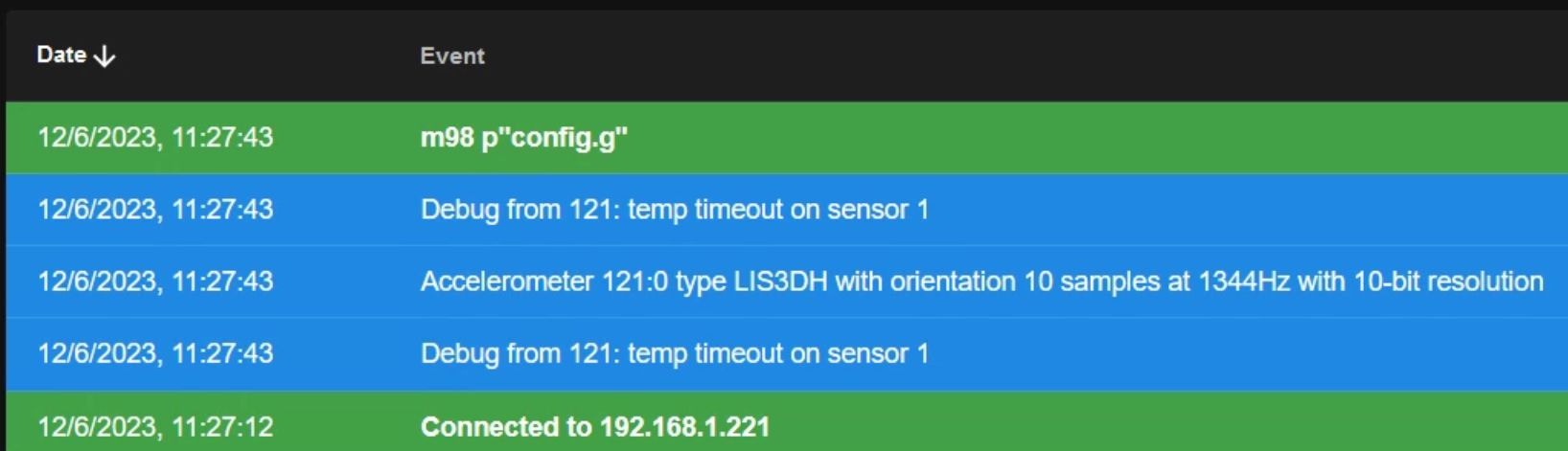
I get an error on sensor 1, after the firmware update to Beta4 (see print screen).
I don't know if it's a real error or just a warning...This is my system: ( Voron 2.4)
RepRapFirmware for Duet 3 MB6HC version 3.5.0-beta.4 (2023-06-08 23:41:30) running on Duet 3 MB6HC v1.01 (SBC mode) Board ID: 08DJM-956BA-NA3TN-6JTDJ-3SJ6S-1T82VDuet TOOL1LC rev 1.1 or later firmware version 3.5.0-beta.4 (2023-06-08 16:22:30)
Bootloader ID: SAMC21 bootloader version 2.4 (2021-12-10)My config.g:
; Note: Core XY Voron 2.4 Duet3 ( SBC RASPBERRY SD 64GB )
;
; ---------- GENERAL PREFERENCES ---------
G4 S2                                                  			    ; WAIT 1 SEC FOR 1LC
G90                                                					; absolute coordinates...
M83                                                					; relative extruder moves
M669 K1                                                 			; Select CoreXY mode
M564 S1 H1                                             			 	; Forbid axis movements when not homed
M575 P1 S1 B57600                              	   					; enable support for Paneldue display
;
; ---------- DRIVES MAPPINGS ----------
;
;       Rear
;	| Z1 | Z2 |   Z2 - Z1
;	-----+-----
;	| Z0 | Z3 |   Z3 - Z0
;	-----+-----
;	   Front
;
M584 X4 Y5 Z0:1:2:3 E121.0											; set drive mapping +++ possible swap X and Y
M569 P0 S1      													; Z0 motor FL goes forwards
M569 P1 S0      													; Z1 motor RL goes backwards
M569 P2 S1      													; Z2 motor RR goes forwards
M569 P3 S0      													; Z3 motor FR goes backwards
M569 P4 S1 										    				; A motor goes forwards
M569 P5 S1 										    				; B motor goes forwards
M569 P121.0 S0      												; E1 motor Extruder goes backwards (scheda 1LC porta 121)
M671 X-67.5:-67.85:422.5:422.5 Y-10:443.8:443.8:-10 S10				; Define Z belts locations (Z0=Front_Left Z1, Z2, Z3...ecc) S10=mm di correzione massima
;
; ---------- DRIVES PARAMETERS ----------
M350 X32 Y32 Z32 E16 I1                            					; configure microstepping with interpolation
M92 X158.5 Y158.5 Z800 E1678          	   							; set steps per mm
M98 P"/macros/print_scripts/setup_printing.g" 			            ; MACRO con parametri di Jerk, speed, accel, corrente.
;
; ---------- AXIS LIMITS ----------
M208 X0 Y0 Z0 S1 									    			; set axis minima (S1)
M208 X340 Y350 Z350 S0 								    			; set axis maxima (S0)
;
; ---------- ENDSTOP ---------
M574 Y2 S1 P"!io1.in"                              					; Configure enstop Y(2) posizione alta dello switch e pin !io1.in invertito
M574 X2 S1 P"!io2.in"                              					; Configure enstop x(2) posizione alta dello switch e pin !io2.in invertito
; M591 P2 C"121.io1.in" S1 D0     									; filament monitor connected to E0_stop su scheda espansione 1LC porta 121
;
; ---------- Z-PROBE ----------
M558 P8 C"!121.io1.in" H20 F500 T5000				    			; set Z probe type inductive (P8),  altezza tastatura (H5), velocità tastatura mm/min (F500), velocità di spostamento mm/min (T6000) su scheda espansione 1LC porta 121
G31 P500 X0 Y24 Z3.32                          						; set Z probe trigger value, PIU' ALTO E' Z PIU' SI AVVICINA AL LETTO
M557 X5:335 Y5:345 S63							   					; define mesh grid (GRIGLIA maglia 5 x 5 con 63mm di spazio)
;
; ----------- HO - HEATERS BED ----------
M308 S0 P"temp0" Y"thermistor" T100000 B4138 A"LETTO"   			; configure sensor 0 as thermistor on pin temp0
M950 H0 C"out1" T0                                 					; create bed heater output on out1 and map it to sensor 0
M307 H0 R0.961 K0.467:0.000 D3.05 E1.35 S1.00 B0					; 28/05/22 DOPO AUTOTARATURA LETTO CON (M303 H0 P1 S90)
M140 H0                                            					; map heated bed to heater 0
;
; ----------- H1 - HEATERS NOZZLE ----------
;
M308 S1 P"121.temp0" Y"thermistor" T100000 B4138 A"ESTRUSORE"		; Configure sensor 1 as thermistor on pin temp1
M950 H1 C"121.out0" T1                                 				; Create nozzle heater output on out0 su scheda espansione 1LC porta 121 and map it to sensor 1
M307 H1 R4.216 K0.327:0.000 D8.25 E1.35 S1.00 B0 V29.4			    ; DOPO AUTOTARATURA NOZZLE CON (M303 H1 P1 S250) il 05/06/23.
M143 H1 S275                                       					; set temperature limit for heater 1 to 275C
;
; ---------- TOOLS ----------
M563 P0 S"TOOLS-0" D0.5 H1 F0                  		                ; DEFINE TOOL 0 =>  P0=Tool 0,  S"..."=Tool name, D0.5=drive 0.5,  H1=heather 1,  F0=fan 0.
G10 P0 X0 Y0 Z0                                    		            ; set tool 0 axis offsets
G10 P0 R0 S0                                       		            ; set initial tool 0 active and standby temperatures to 0C
;
;	---------- FAN 0 VENTOLA RAFFR. STAMPA PWM (out4) 24v ----------
M950 F0 C"121.out2" Q500							                ; Fan 0 su 121.out2, use PWM, using 121.out2
M106 P0 C"VENTOLA FILO" S0.0 H-1                     				; set FAN_0 name and value.
;
; ---------- FAN 1 VENTOLA HOTEND (out8) 24v ----------
M950 F1 C"121.out1" Q500							                ; Fan 0 su 121.out2, use PWM, using 121.out2
M106 P1 C"HOTEND" H1 L0.1 X0.5 B0.3 T60:250  	                    ; PARAMETRICA Termostatica ( da 30% a 100% con temp. da 70°C a 250°C )
;
; ---------- FAN 2 VENTOLA MCU PWM (out5) 24v ---------
M308 S3 Y"mcu-temp" A"MCU" 						   					; configure sensor 3 as thermistor for MCU
M950 F2 C"!out5+out5.tach" 											; Fan 2 su out5, use PWM (needs ! inverted), using out5.tach
M106 P2 C"VENTOLA MCU" L0.1 X0.8 B0.1 T26:35 H3		    			; set FAN_2 value  T26:32°C  velocità ventola L-10% X-80%
;
; ---------- FAN 3 VENTOLA PWM RASPBERRY (out6) 24v ---------
M308 S4 P"temp2" Y"thermistor" T100000 B4138 A"RASPBERRY" 			; Configura il sensore 4 (S4) come riscaldatore sul pin temp2 con nome RASPBERRY
M950 F3 C"!out6+out6.tach" 											; Fan 3 su out6, use PWM (needs ! inverted), using out6.tach
M106 P3 C"VENTOLA RASPBERRY" L0.1 X1.0 B0.9 T35:45 H4				; set FAN_3 value  T35:45°C  velocità ventola L-10% X-100%
;
; ---------- PORT 1 RELE' ACCENSIONE (io4.out) IO PORT PWM ----------
M950 P1 C"io4.out" Q500												; allocate GPIO PORT.1 to io4.out at 500Hz
; M42 P1 S0.0  														; Printer OFF set 0% PWM on GPIO port 1
; M42 P1 S1.0  														; Printer ON set 100% PWM on GPIO port 1
;
; ---------- ACCELEROMETRO ----------
M955 P121.0 I10                                         			; ACCELEROMETRO SU SCHEDA 1LC (I10 = orientamento scheda)
;
; ---------- PULSANTE FISICO CHE ATTIVA MACRO ----------
; M950 J5 C"io5.in"
;      										                        ; Crea trigger n°5 su porta "121.button0"
M950 J5 C"121.button0"         						    		    ; Crea pin 5 su porta 121.button0 della scheda 1LC
M581 P5 T2 S1 R0													; P5=pin 5 creato con M950 (J5), T2=Trigger logico a cui associare gli ingressi, S1=funziona da inattivo ad attivo, R0=attivo in ogni momento
;  	Qualsiasi numero di trigger # maggiore di 1 provoca l'esecuzione del file della macro sys/trigger2.g (T2)
M950 J6 C"121.button1"                                              ; Crea trigger n°6 su porta "121.button0"
M581 P6 T3 S1 R0                                                    ; Crea pin 56 su porta 121.button1 della scheda 1LC
;
;---------- EMERGENCY BUTTON ----------
; M950 J7 C"121.button0" 											; Crea trigger n°7 su porta "121.button0"
; M581 P7 T4 S1 R0 													; configurara pin IN N°7 (P7), ed aziona trigger 4
;
; ---------- NEOLED ----------
; M150 X1 Q3000000													; SPI frequency to 3MHz
M950 E0 C"led" T1
M98 P"0:/macros/7C-NEOLED ITALIA.g"									; Esegui la MACRO "7C-NEOLED ITALIA.g"
; M150 R255 U255 B255 P90 S25 F0									; Luce bianca per 25 led potenza 90 su 255
; M150 R0 U0 B255 P200 S24 F0										; Set luce BLU per 24 LED
;
; ---------- MISCELLANEUS ----------
M912 P0 S-1									   					    ; parametro per tarare la temperatura della MCU (-1°C)
; M911 S24.5 R24.9 P"M913 X0 Y0 G91 M83 G1 Z3 E-2 F500" 			; Autosalvataggio stampa per mancanza di corrente, sospende a 25.0v e riparte a 25.8v
M300 S2500 P3000								   					; Emette suono a S=2500Hz per P=3 secondi
T0                                             	        			; select first tool ACTIVE
; ---------- END SCRIPT -----------
;
;
; ---------- FUNZIONI NON PIU' ATTIVE ----------
;
; ---------- FAN 4 LUCE LED su RISCALDATORE (out3) 24v ----------
;M950 F4 C"out3" Q1000						       					;create FAN_4 on pin out3 and set its frequency at 1000hz
;M106 P4 C"LUCE LED" S0.1            			   					;LED ON AL 10%
;M106 P4 S0.0									   					;PER SPEGNERE LED
;
; ---------- SERVOCOMANDO RC ----------
; M950 S2 C"out9" 													; assign GPIO port 2 to out9 (Servo header)
; M280 P2 S100 														; S25 fine corsa DX S175 fine corsa SX S100 centro corsa
;
Do I need to change any parameters? Before with Beta3 I didn't get any warnings...
-
@Gianluca just to make sure: Did you also update the firmware on the toolboard?
<>RatRig V-Minion Fly Super5Pro RRF<> V-Core 3.1 IDEX k*****r <> RatRig V-Minion SKR 2 Marlin<>
-
@Gianluca you can ignore that warning if sensor 1 is giving sensible readings. I have seen that warning too. In previous firmware versions there wasn't anywhere for that message to be displayed, so I don't think it is new.
I have created a Github issue for this, https://github.com/Duet3D/RepRapFirmware/issues/866.
closed Timeout message from tool board sensor #866
Duet WiFi hardware designer and firmware engineer
Please do not ask me for Duet support via PM or email, use the forum
http://www.escher3d.com, https://miscsolutions.wordpress.com -
@oliof Yes, by SBC...
-
@dc42 Thank you for your great work!!!
