Yaskawa Servo Drive Connection Development
-
Well, already I found one problem. The above schematic seems to satisfy the drivers' 3.3V step/dir requirement, however the current would be nearly 20mA, and the 1XD's current limit is 10mA.
So, mmm, I dunno. I'll be back...
-
@Maestro for the step and direction inputs, driving then from a 6XD through 100 ohm series resistors should work. The 6XD enable outputs are not 24V tolerant. However, as they are servos you might decide that enabling/disabling the motors individually is not required and you could use one of the optically isolated outputs as an enable signal instead. It wouldn't be automatic so you would have to enable them using commands in config.g or in your homing files, and disable them if required in stop.g.
Alternatively you could use a resistor and NPN transistor or mosfet to convert the Enable output to be 24V tolerant.
HTH David
Duet WiFi hardware designer and firmware engineer
Please do not ask me for Duet support via PM or email, use the forum
http://www.escher3d.com, https://miscsolutions.wordpress.com -
@dc42 Thanks for the input, David, I appreciate it. Good news on the resistors, less so on the enable, but not unexpected.
Since I'm planning to go to the trouble of making a breakout board already, a few components to allow the use of the dedicated enable signals seems worthwhile, so I'll head down that path.
And since the current capacity of the 6XD's drivers is a better match for the servo drives, I'll go back to the route of a 6XD board, rather than 1XD.
-
@Maestro the 6XD also supports higher step rates than the 1XD, so that is another reason to use it.
Duet WiFi hardware designer and firmware engineer
Please do not ask me for Duet support via PM or email, use the forum
http://www.escher3d.com, https://miscsolutions.wordpress.com -
@dc42 Yes, I did see that. And I was trying not to fall into the more steps = automatically better trap. But, let's face it, it is...
I think I have only one question remaining. For the error input pins, I'm looking at the 6XD schematic files and I can't work out whether additional protection is needed to connect from +5V to the alarm-out optocoupler and back to Dx_ERR(-). Unlike all the other connections, the drive's alarm-out has no current-limiting resistor (see final, "Photocoupler Outputs" reference image above), so I had originally put a 500ohm resistor on Dx_ERR(-), but now wonder if this is unneeded, or should be a lower resistance of ~250ohm?
-
@Maestro you can connect the alarm phototransistor output directly to the alarm input on the Duet (ALM+) and ground on the same connector (ALM-).
Duet WiFi hardware designer and firmware engineer
Please do not ask me for Duet support via PM or email, use the forum
http://www.escher3d.com, https://miscsolutions.wordpress.com -
Thanks @dc42 , that makes things one resistor simpler.
-
Well, it now exists.
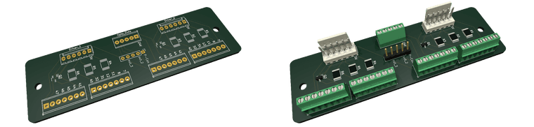
All truly necessary functions can be controlled with the 6XD driver inputs and +24V. With two opto-outs, alarm reset and torque-limiting can also be controlled, and two additional opto-outs can jumper-select between addressing P-Control mode or one of two free breakout pins for user-selected functions.
A GitHub repo has been set up with readme, schematic file, and pcb file. There are a lot of used Yaskawa drives out there; maybe this will help some people who want to try the servo route.
Thanks @dc42 and @chrishamm for the help!
-
@Maestro looks good!
FWIW in designing the 6XD we made provision to attach a daughter board over the driver output connectors, to allow for converting the signals for drivers that wanted differential drive or 24V drive.
Duet WiFi hardware designer and firmware engineer
Please do not ask me for Duet support via PM or email, use the forum
http://www.escher3d.com, https://miscsolutions.wordpress.com -
@dc42 Gah! I saw those holes in the 6XD board by the drivers and was wondering what one would mount there. I don't know how I didn't put two and two together. Well, there may be a daughterboard version coming in the near future!