Duet Toolbaord 1LC, TAP Probe, Z Probe not triggered
-
Hi everybody, i am trying to use my Duet Toolboard 1LC on my Voron 2.4 with the "new" TAP probe (Omron D2FP-FN sensor) but the Probe will never be triggered.
I used the io.0 pin, and connected 5V, io.0.in and GND. The Toolbaord only supports Mode 8 and Mode 9 for probing so i used Mode 8 for the Omron D2FP-FN sensor.
My X and Y endstops are sensorless Homing.
Thanks for helping me in this case
Config:
; Configuration file for Duet 3 (firmware version 3.3)
; executed by the firmware on start-up
;
; generated by RepRapFirmware Configuration Tool v3.3.5 on Wed Nov 17 2021 22:28:52 GMT+0100 (Mitteleuropäische Normalzeit)

; General preferences

G4 S2 ; wait for expansion boards to start


M575 P1 S1 B57600                            ; enable support for PanelDue
G90                                          ; send absolute coordinates...
M83                                          ; ...but relative extruder moves
M550 P"Duet 3"                               ; set printer name
M669 K1                                      ; select CoreXY mode

; Drives
M569 P0.5 S1                                 ; physical drive 0.5 goes forwards
M569 P0.4 S1                                 ; physical drive 0.4 goes forwards


; Drives for Z
M569 P0.0 S1                                    	; Front left
M569 P0.1 S0                                       	; Back left
M569 P0.2 S1                                       	; Back right
M569 P0.3 S0                                       	; Front right


M569 P121.0 S0                                        ; physical drive 1.0 goes backwards


M584 X0.4 Y0.5 Z0.0:0.1:0.2:0.3 E121.0             ; set drive mapping LF,LH,RH,RV


M350 X16 Y16 Z16 E16 I1                  	; configure microstepping with interpolation
M92 X80.00 Y80.00 Z400.00 E820.00         			; set steps per mm
M566 X600.00 Y600.00 Z60.00 E8000.00       			; set maximum instantaneous speed changes (mm/min)
M203 X15000.00 Y15000.00 Z3000 E15000		       	; set maximum speeds (mm/min)
M201 X1500.00 Y1500.00 Z350.00 E1800.00    			; set accelerations (mm/s^2)
M204 P1500 T2000									; set printing acceleration and travel acceleration
M906 X1000 Y1000 Z1500 E1200 I60                    ; set motor currents (mA) and motor idle factor in per cent
M84 S30

; Axis Limits
M208 X0 Y0 Z-0.2 S1                           ; set axis minima
M208 X440 Y440 Z400 S0                     	  ; set axis maxima

; Endstop Sensorless
M574 X1 S3
M574 Y1 S3

M915 X Y R0 F0

; Z-Probe
M558 P8 C"121.io0.in" H5 F120 T6000
G31 P500 X0 Y0 Z0

M671 X330:330:10:10 Y380:80:80:380 S5
M557 X10:330 Y80:430 P5

; Heater
M308 S0 P"temp0" Y"thermistor" T100000 B4138 ; configure sensor 0 as thermistor on pin temp0
M950 H0 C"out0" T0                       ; create bed heater output on out0 and map it to sensor 0
M307 H0 B0 S1.00                             ; disable bang-bang mode for the bed heater and set PWM limit
M140 H0                                             ; map heated bed to heater 0
M143 H0 S140                                   ; set temperature limit for heater 0 to 120C

; Temp Sensor
M308 S1 P"121.temp0" Y"pt1000"           ; configure sensor 1 as thermocouple via CS pin spi.cs0
M950 H1 C"121.out0" T1               ; create nozzle heater output on 1.out0 and map it to sensor 1
M307 H1 B0 S1.00                             ; disable bang-bang mode for heater  and set PWM limit
M143 H1 S400                                 ; set temperature limit for heater 1 to 280C

; Heater model parameters
M307 H0 R0.590 C602.700:602.700 D4.10 S1.00 V24.0 B0
M307 H1 R3.176 K1.020:0.000 D5.18 E1.35 S1.00 B0 V24.0


; Fans
M950 F0 C"121.out1" Q250                       ; create fan 0 on pin out7 and set its frequency
M106 P0 C"Part Fan"  S0 H-1                   ; set fan 0 value. Thermostatic control is turned off

M950 F1 C"121.out2" Q500                         ; create fan 1 on pin out8 and set its frequency
M106 P1 C"Hotend Fan" S1 H1 T45           ; set fan 1 value. Thermostatic control is turned on

M950 F2 C"out9" Q150                         ; create fan 2 on pin out9 and set its frequency
M106 P2 C"Chamber Fan"                      	     ; set fan 0 value. Thermostatic control is turned off

; Tools
M563 P0 D0 H1 F0
G10 P0 X0 Y0 Z0
G10 P0 R0 S0

; Custom settings are not defined

;M564 H0
;M501
M302 P1
Homeall
; homeall.g
; called to home all axes
;
; generated by RepRapFirmware Configuration Tool v3.3.5 on Wed Nov 17 2021 22:28:52 GMT+0100 (Mitteleuropäische Normalzeit)

M400
M913 X70 Y70
M400
G91 ; relative positioning

G1 H2 Z10 F12000
G1 H1 X-450 F5000
G1 H1 Y-450 F5000
G90
M400
M913 X100 Y100
M400

G1 X200 Y200 F6000    .
G30
Homez
; homez.g ; called to home the Z axis ; ; generated by RepRapFirmware Configuration Tool v3.3.5 on Tue Nov 23 2021 18:23:01 GMT+0100 (Mitteleuropäische Normalzeit) G90 G1 X200 Y200 F6000 G30 ; Z probe quickly (1 of 2 passes). -
This post is deleted! -
@DMMAGIC What value does the Z-Probe report in DWC? Does it change when triggered/not triggered?
Looking at the datasheet https://components.omron.com/eu-en/sites/components.omron.com.eu/files/datasheet_pdf/B153-E1.pdf I'd guess that it is wired NO (normally open), but RRF generally expects NC (normally closed). Flip the signal by changing your probe configuration to include a
!in the probe name:M558 P8 C"!121.io0.in" H5 F120 T6000Check that the Z-Probe reports 0 when not triggered, and 1000 when triggered.
Ian
Bed-slinger - Mini5+ WiFi/1LC | RRP Fisher v1 - D2 WiFi | Polargraph - D2 WiFi | TronXY X5S - 6HC/Roto | CNC router - 6HC | Tractus3D T1250 - D2 Eth
-
@Herve_Smith Thx for your fast support.
Physically check was good.
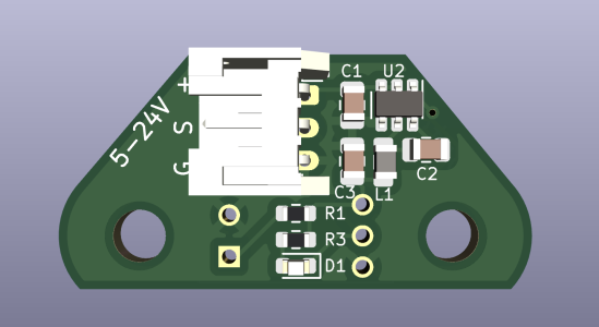
My TAP from Chaoticlab has 3 wires: S V/+ G (Signal, Voltage, Ground)
So i wired it on my Toolboard io.0 connector this way:
S -> io.in
V/+ -> +5V
G -> GNDThis is the PCB mount of the Omron sensor
I tested the Probe "Handtriggered" while sending M119, always the same result:
M119 Endstops - X: not stopped, Y: not stopped, Z: no endstop, Z probe: not stopped -
@droftarts Z probe on DWC reports always "not triggered".
Yes, they are often NO sensors. That would be my next step to invert this.
-
i solved the Problem. It was simply necessary to ativate the pullup resistor...
Thx for the help!
-
@DMMAGIC I don't think that's the correct PCB; the pinout of the Omron D2FP-FN is different from the pin holes shown on that PCB. Have you got a link where this PCB came from?
Ian
-
@DMMAGIC said in Duet Toolbaord 1LC, TAP Probe, Z Probe not triggered:
i solved the Problem. It was simply necessary to ativate the pullup resistor...
Thx for the help!
Io0_in has a permanent pullup resistor, so that should not have been necessary. Our test equipment checks for the presence of that resistor. Is it a genuine Duet3D tool board?
Duet WiFi hardware designer and firmware engineer
Please do not ask me for Duet support via PM or email, use the forum
http://www.escher3d.com, https://miscsolutions.wordpress.com -
@dc42 Hi, yes it is. Ive ordered the board fro this side:
https://www.dold-mechatronik.de/3D-Druck-Duet3D -
@DMMAGIC can you provide a close up photo of the tool board showing the components close to the IO1 connector?