White Screen of Death despite flashing panel
-
-
@sawalzel said in White Screen of Death despite flashing panel:
the 4 wire connecter which worked with it flashing lines across the screen at the time.
Can you test the 4 wire connector again?
Which Duet board are you connecting it to? Can you show the connections at both ends?
-
@Phaedrux Yes the four wire connecter shows the white screen like the image before.
Connecting to the duet 3 mb6xd.
Do you mean like the wire connections from both sides of the ribbon cable?
-
@sawalzel said in White Screen of Death despite flashing panel:
Do you mean like the wire connections from both sides of the ribbon cable?
Yes. Just want to verify that the ribbon cable orientation is correct. Same for the 4 wire.
It's strange that the display works fine when connected to USB power, but not when connected to the Duet.
@sawalzel said in White Screen of Death despite flashing panel:
duet 3 mb6xd.
Which port did you use for the 4wire connection?
Review the connection guide here: https://docs.duet3d.com/en/User_manual/Connecting_hardware/Display_PanelDue
-
@Phaedrux Sorry for the delay. I thought it was a problem with the board so I ordered another duet 3 mb6xd but that has not solved the problem. When I connect my computer through the usb-c and the 24v PSU the panel works for about 15 seconds then turns black.
-
@Phaedrux I connected to Io_0 like the instructions say and It still does not work.
-
@sawalzel it sounds to me that the PanelDue is not getting enough 5V power from the Duet. Normally I'd suggest this indicates a problem with the cable between the Duet and the PanelDue. However, if it happens with both the ribbon cable and the 4-pin cable then it seems unlikely that both cables would be faulty. So either the PanelDuet now needs more power than before ( but that's not the case if a new PanelDue has the same problem) or the Duet is no longer able to supply the required power. Which Duet is it? Have you connected anything else to the Duet recently that draws power from its 5V or 3.3V supplies? Are any components on the Duet getting hot, when the machine is idle?
Duet WiFi hardware designer and firmware engineer
Please do not ask me for Duet support via PM or email, use the forum
http://www.escher3d.com, https://miscsolutions.wordpress.com -
@dc42
I have a duet 3 mb6xd and replaced the board not the panelDue. I have tried the ribbon cable provided as well as another ribbon cable and still no change. When nothing is connected to the board it connects to the panel as it should. I don't believe anything new has been connected that draws power from the 3.3 or 5V. Nothing is getting hot from what I can tell.I currently have 3 external drivers, 3 AC SSR connected, 1 endstop, and 3 pt100 sensors with the daughterboard.
-
@dc42
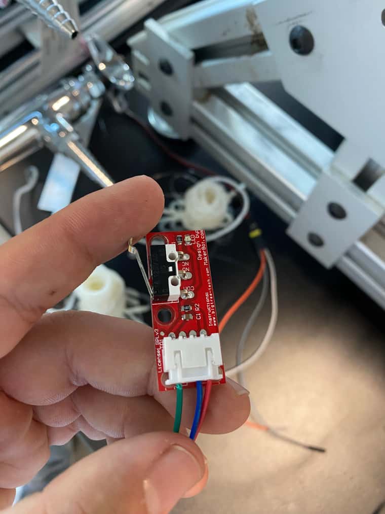
I figured out the problem. You were correct that it was not getting the 5V and after unplugging stuff to figure out what was the problem, I found the endstop was. I'm using these small little red ones as you can see in the link. I don't know why these are the problem but if I need to change endstops please let me know any ones that are confirmed to work with a duet board. -
How did you have them connected?
Should be like this: https://docs.duet3d.com/en/User_manual/Connecting_hardware/Sensors_endstops#makerbot-mechanical-endstop-v12
-
@Phaedrux
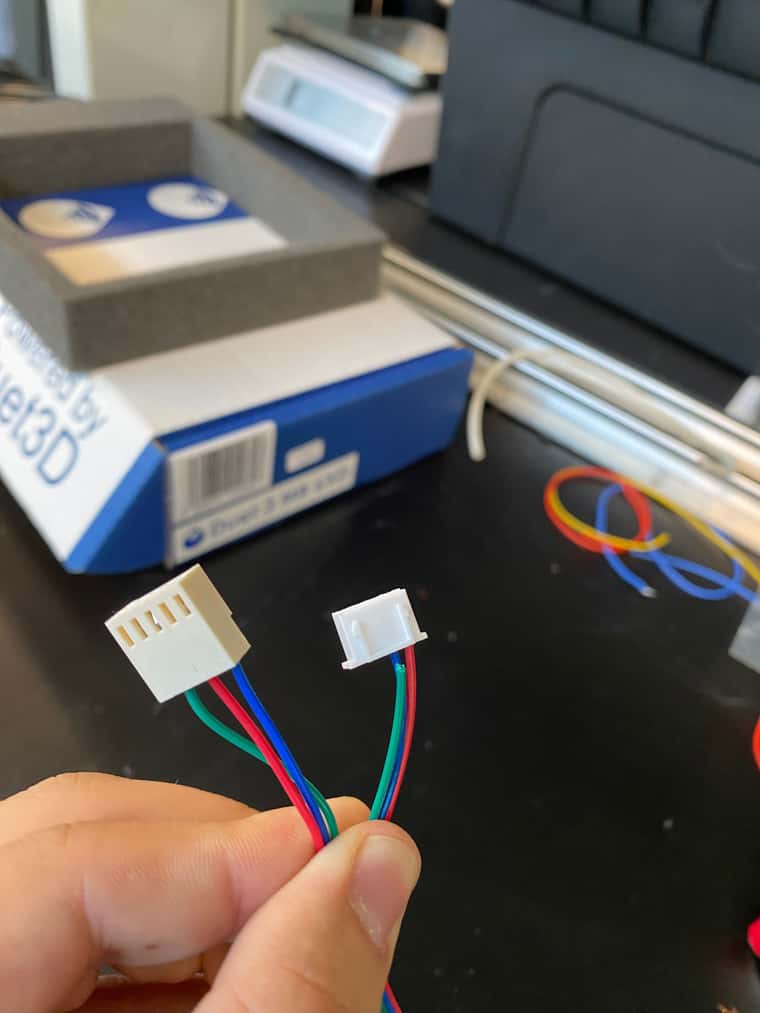 image url
Tried my best to show everything but to the board used io_in(green), ground(red), and 3.3V(blue). To the end stop the wiring is the same to my understanding with the signal being normally closed.
-
@sawalzel the red wire is connected to either pin 1 or pin 4 of the endstop switch, which according to the documentation that @Phaedrux linked to is either Vcc or output, not ground.
Duet WiFi hardware designer and firmware engineer
Please do not ask me for Duet support via PM or email, use the forum
http://www.escher3d.com, https://miscsolutions.wordpress.com -
@dc42
I have tried other permutations of the wires and that was the picture was the only orientation that worked. Now if I plugin the endstop the panel doesn't work so I can't really try anything.
What endstops do you know that work with duet? -
I use the same endstops, so that style does work, but it sounds like they are wired incorrectly such that it's shorting, or drawing too much current.
Can you show a picture of it actually connected so we can see both ends?
-
@Phaedrux
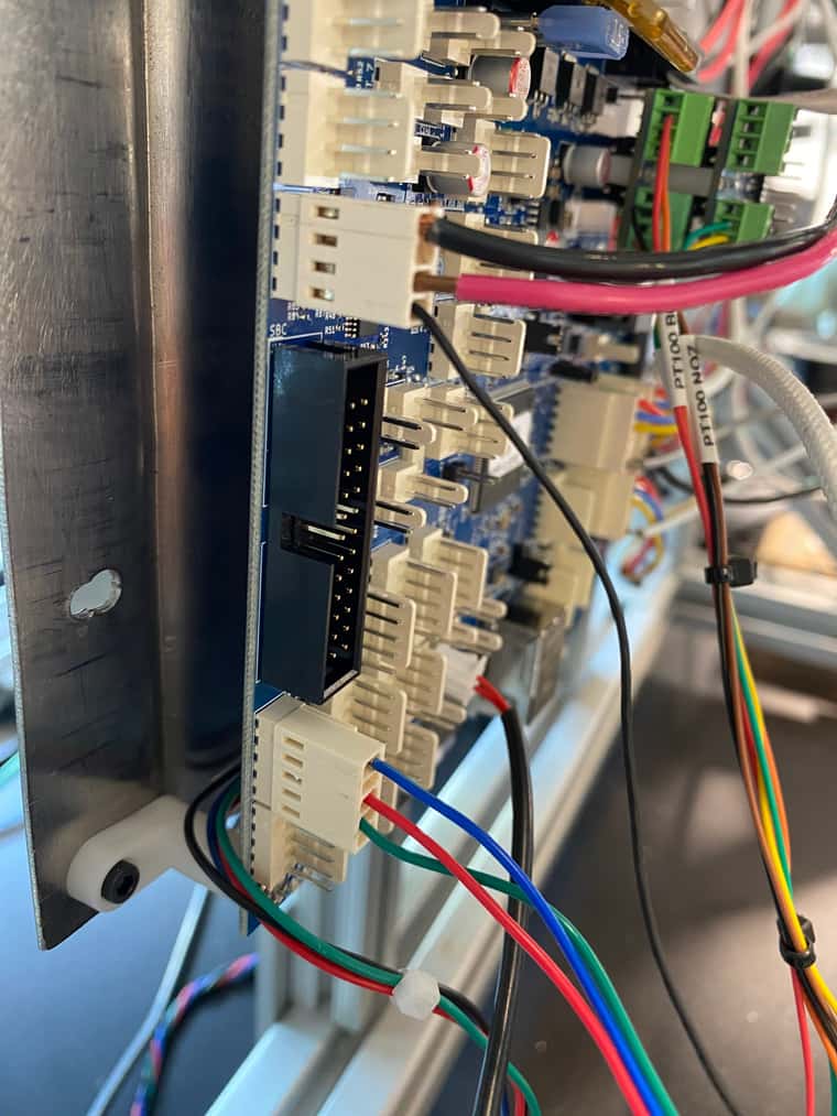
The blue, red, green connections towards the bottom is the endstop. -
Makerbot endstop pin number Function Duet 3 IO_x pin marking Duet 2 endstop pin marking 1 VCC 3V3 3V3 2 or 3 GND GND GND 4 Output IO_x_IN STP Unfortunately the pin markings on the Makerbot endstop board are hidden underneath the connector. Pin 1 is next to the long edge of the board that does not have the microswitch on it, and pin 4 is nearest the edge with the microswitch.Can you see markings on the endstop indicating which pin is which?
If the description from the documentation matches your endstop pin 1 would be on the right side of the endstop in your picture with the red cable in it. Which based on the table should be VCC 3.3v, but you have that wired into the middle pin on the Duet connector, which is ground.
The blue wire in the middle should be ground, but you have it wired to 5v external.
Pin 4 with the green wire is signal and it looks like that one is correct.
So I think you're basically shorting the 5v rail.

So I think you should move the red wire to the 3.3v pin on the duet connector and move the blue wire to ground. But to be sure you should identify which pin is which on the endstop itself. You may need to lift up the white connector a little bit to see the silk screen printing under neath it. Or maybe they have it labeled on the back side.