More problems
-
@timschneider said in More problems:
@invertmast
OK, i double checked my previous posts about the protocol and checksum and so on.the variables are reset via the state machine state idle and the protocol does provide a parity check. Based on your M122 output there are alot of error frames and parity errors from your filament sensor.
=== Filament sensors ===
Extruder 0: pos 146.95, errs: frame 311476 parity 877 ovrun 0 pol 3 ovdue 0
it should be more like
=== Filament sensors ===
Extruder 0: pos 107.23, errs: frame 0 parity 0 ovrun 0 pol 0 ovdue 0
so I still think it is an ESD or bad connection problem.
Hope this will help you.
That M122 was with a different sensor. the one that was originally in the housing designed by a member here..
Here is the M122 with the sensor currently mounted on this printer and the one giving the current problems (the one with the housing supplied by Duet).
other than the sensor, everything else is identical on this printer and all posts since the Sept. 4th are of this sensor.
m122 === Diagnostics === RepRapFirmware for Duet 2 WiFi/Ethernet version 3.4.6 (2023-07-21 14:08:28) running on Duet WiFi 1.02 or later + DueX5 Board ID: 08DGM-956GU-DJ3SJ-6J9DD-3SD6S-9UPZH Used output buffers: 9 of 26 (26 max) === RTOS === Static ram: 23896 Dynamic ram: 76636 of which 12 recycled Never used RAM 7960, free system stack 106 words Tasks: NETWORK(ready,15.9%,211) HEAT(notifyWait,0.1%,333) Move(notifyWait,1.2%,268) DUEX(notifyWait,0.0%,24) MAIN(running,82.7%,421) IDLE(ready,0.1%,30), total 100.0% Owned mutexes: === Platform === Last reset 00:20:27 ago, cause: power up Last software reset at 2023-09-17 10:38, reason: User, GCodes spinning, available RAM 11600, slot 0 Software reset code 0x0003 HFSR 0x00000000 CFSR 0x00000000 ICSR 0x0041f000 BFAR 0xe000ed38 SP 0x00000000 Task MAIN Freestk 0 n/a Error status: 0x1c Aux0 errors 0,1,0 Step timer max interval 0 MCU temperature: min 21.2, current 28.5, max 29.0 Supply voltage: min 23.6, current 24.1, max 24.8, under voltage events: 0, over voltage events: 0, power good: yes Heap OK, handles allocated/used 99/1, heap memory allocated/used/recyclable 2048/24/12, gc cycles 0 Events: 0 queued, 0 completed Driver 0: ok, SG min 0 Driver 1: standstill, SG min n/a Driver 2: ok, SG min 0 Driver 3: stalled, SG min 0 Driver 4: standstill, SG min n/a Driver 5: ok, SG min 0 Driver 6: ok, SG min 0 Driver 7: ok, SG min 0 Driver 8: ok, SG min n/a Driver 9: standstill, SG min n/a Driver 10: Driver 11: Date/time: 2023-09-22 09:51:13 Cache data hit count 4294967295 Slowest loop: 220.62ms; fastest: 0.17ms I2C nak errors 0, send timeouts 0, receive timeouts 0, finishTimeouts 0, resets 0 === Storage === Free file entries: 9 SD card 0 detected, interface speed: 20.0MBytes/sec SD card longest read time 1.2ms, write time 383.9ms, max retries 0 === Move === DMs created 83, segments created 30, maxWait 357293ms, bed compensation in use: mesh, comp offset 0.000 === MainDDARing === Scheduled moves 4219, completed 4206, hiccups 0, stepErrors 0, LaErrors 0, Underruns [0, 0, 0], CDDA state 3 === AuxDDARing === Scheduled moves 0, completed 0, hiccups 0, stepErrors 0, LaErrors 0, Underruns [0, 0, 0], CDDA state -1 === Heat === Bed heaters 0 -1 -1 -1, chamber heaters -1 -1 -1 -1, ordering errs 0 Heater 0 is on, I-accum = 0.0 Heater 1 is on, I-accum = 0.7 === GCodes === Segments left: 1 Movement lock held by null HTTP is idle in state(s) 0 Telnet is idle in state(s) 0 File is doing "G1 X233.050 Y245.301 E2.07967" in state(s) 0 USB is idle in state(s) 0 Aux is idle in state(s) 0 Trigger is idle in state(s) 0 Queue is idle in state(s) 0 LCD is idle in state(s) 0 Daemon is idle in state(s) 0 Autopause is idle in state(s) 0 Code queue is empty === Filament sensors === Extruder 0: pos 250.66, errs: frame 0 parity 0 ovrun 0 pol 0 ovdue 0 === DueX === Read count 1, 0.05 reads/min === Network === Slowest loop: 387.30ms; fastest: 0.00ms Responder states: HTTP(0) HTTP(0) HTTP(0) HTTP(0) FTP(0) Telnet(0) HTTP sessions: 1 of 8 = WiFi = Interface state: active Module is connected to access point Failed messages: pending 0, notready 0, noresp 0 WiFi firmware version 1.27 WiFi MAC address 5c:cf:7f:76:63:7a WiFi Vcc 3.40, reset reason Turned on by main processor WiFi flash size 4194304, free heap 25760 WiFi IP address 192.168.4.29 WiFi signal strength -47dBm, mode 802.11n, reconnections 0, sleep mode modem Clock register 00002002 Socket states: 0 0 0 0 0 0 0 0 -
@invertmast
ok, i understand. Do you also have an M122 output when the filament sensor is producting wrong values?And have you been able to get some pictures of the connections? And you are routing the signals through an ethernet cable, so some sort of twisted pair cable, which signal is running in a pair? Is the Data-Line running next to the GND of the Filament Sensor in a twisted pair? If not, that can be the problem.
Tim
-
@timschneider said in More problems:
@invertmast
ok, i understand. Do you also have an M122 output when the filament sensor is producting wrong values?And have you been able to get some pictures of the connections? And you are routing the signals through an ethernet cable, so some sort of twisted pair cable, which signal is running in a pair? Is the Data-Line running next to the GND of the Filament Sensor in a twisted pair? If not, that can be the problem.
Tim
the M122 i posted last was of the sensor as it was giving problems.
Signal and ground are in seperate twisted pairs.
In a twist, i have been doing a decent amount of prints at higher speed (55-75mm/sec) and lower layer heights (.2 to .4mm) and the amount of inconsistency in the min/max values has essentially disappeared. All of the above issues were with printing at 30-32mm/sec and .6mm layers. It seems that the issues may be related to flow rate and movement of the filament through the sensor.
I do have that photo, i'll get posted from my phone here shortly.
-
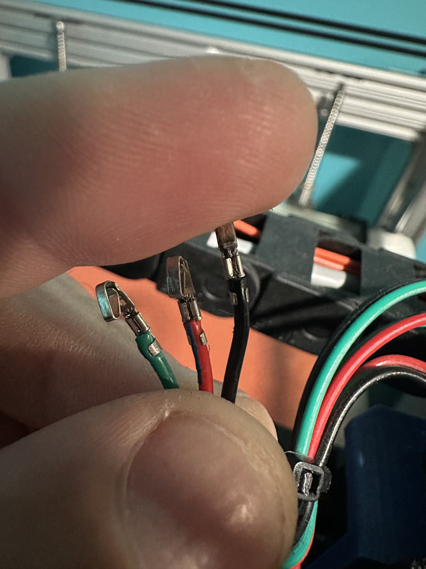
Here is the photo of the monitor pin crimps:
I have found that with a lower layer height than the .6mm i had been using, the frequency of random pauses has decreased, but they are still common enough to be a nuisance. They also seem to become more frequent as the sensor errors begin to accumulate.
-
@invertmast I had a TON of similar problems with my sensor. The main fix is kinda easy. Design a housing that will hard mount the sensor to the extruder. You want this housing to be rigid to the extruder to absolutely constrain the filament between the drive gear and the sensor. My theory here is that the constant movement wears the bowden enough to allow the sensor housing to move and effect readings. This brought my readings to 90%-110% with no more false readings.
I had problems with wires too. Small wires don't like movement, especially at sharp points, let alone constantly moving. Strain relief really helps here. The best way I have found is to put some RTV silicone into a syringe. Use a needle that will allow you to inject silicone into the connector ends. Don't fill it completely up, just enough to encapsulate up to the crimp, and then some more on the outside of the connector. You could probably even print up some strain relief molds if you want to be really slick. You "could" use hot glue if your printer isnt in an enclosure, but I wouldn't recommend it. If it gets enough radiant heat from the bed, it will remelt and seep into every nook and cranny of the connector, even gluing itself to the OTHER connector it's plugged into. Ask me how i know...
The absolute best way to strain relief is Silastic. That is the glue used inside commercial electronics for strain relief of wires and capacitors. But every time I've looked into it, I've found it to be more of an empty rabbit hole and the products I've found vary too wildly in their specs, availability, and cost so I just gave up and went with rtv silicone.
![PXL_20231018_033955711[1].jpg](/assets/uploads/files/1697601325037-pxl_20231018_033955711-1-resized.jpg)
-
@invertmast
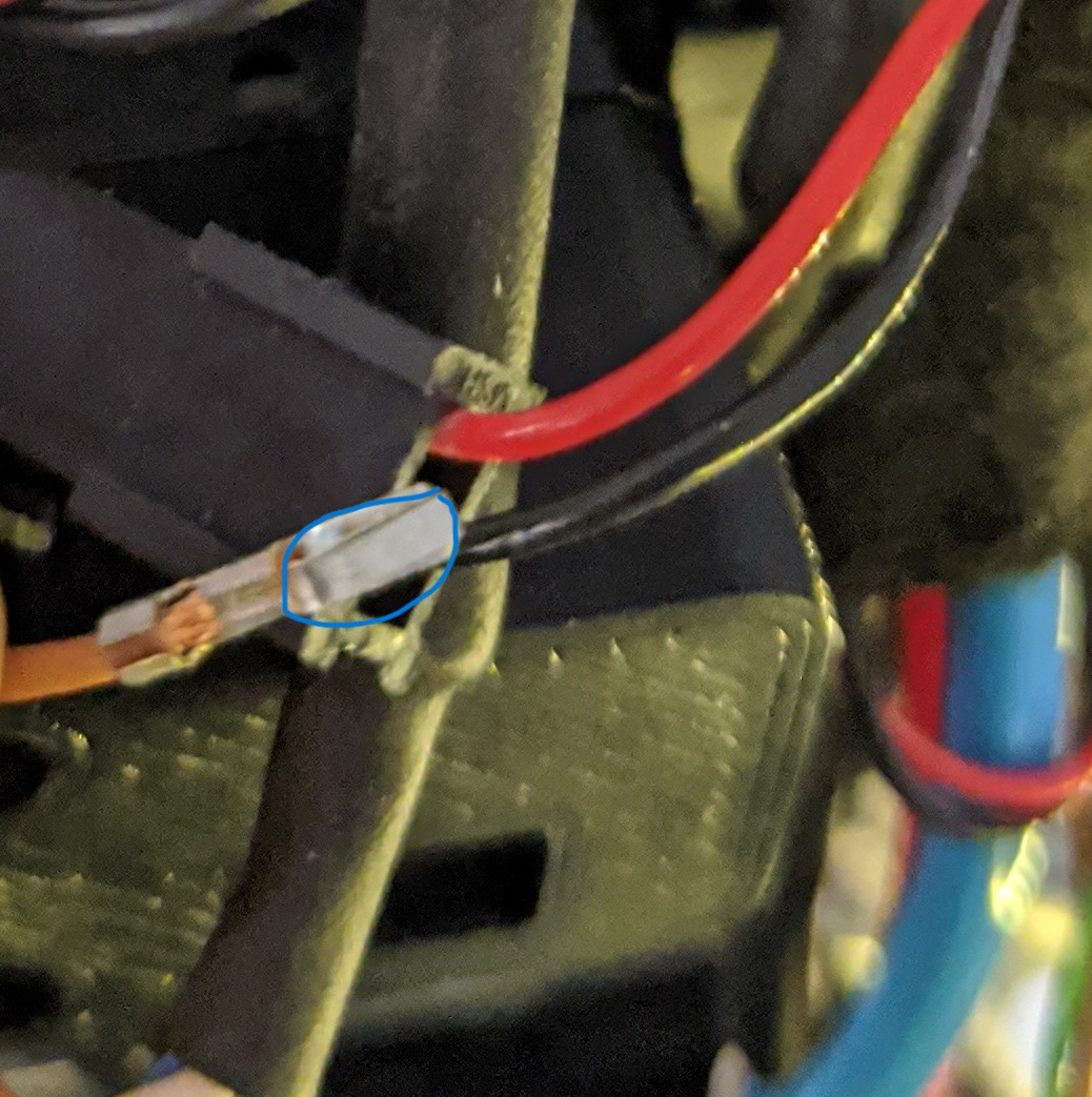
that looks intresting, either you plugged and unplugged the connector quite often or it could be the problem @macguyver pointed outthis is a picture of a contact with strain relief after 100+h of printing, there are no such scratches.
-
@macguyver said in More problems:
@invertmast I had a TON of similar problems with my sensor. The main fix is kinda easy. Design a housing that will hard mount the sensor to the extruder. You want this housing to be rigid to the extruder to absolutely constrain the filament between the drive gear and the sensor. My theory here is that the constant movement wears the bowden enough to allow the sensor housing to move and effect readings. This brought my readings to 90%-110% with no more false readings.
I had problems with wires too. Small wires don't like movement, especially at sharp points, let alone constantly moving. Strain relief really helps here. The best way I have found is to put some RTV silicone into a syringe. Use a needle that will allow you to inject silicone into the connector ends. Don't fill it completely up, just enough to encapsulate up to the crimp, and then some more on the outside of the connector. You could probably even print up some strain relief molds if you want to be really slick. You "could" use hot glue if your printer isnt in an enclosure, but I wouldn't recommend it. If it gets enough radiant heat from the bed, it will remelt and seep into every nook and cranny of the connector, even gluing itself to the OTHER connector it's plugged into. Ask me how i know...
The absolute best way to strain relief is Silastic. That is the glue used inside commercial electronics for strain relief of wires and capacitors. But every time I've looked into it, I've found it to be more of an empty rabbit hole and the products I've found vary too wildly in their specs, availability, and cost so I just gave up and went with rtv silicone.
The monitor is rigidly mounted to the carriage assembly. there is only a 25mm gap between the extruder and the filament monitor.
as for strain relief, the wires between the ethernet breakout board and the filament monitor are less than 100mm long and are rigidly attached at both ends. there is little to no movement of them.
-
@timschneider said in More problems:
@invertmast
that looks intresting, either you plugged and unplugged the connector quite often or it could be the problem @macguyver pointed outthis is a picture of a contact with strain relief after 100+h of printing, there are no such scratches.
this one has well over 1,000hrs of printing time and the connector has been removed countless times chasing problems with two different monitors..
-
@invertmast said in More problems:
@macguyver said in More problems:
@invertmast I had a TON of similar problems with my sensor. The main fix is kinda easy. Design a housing that will hard mount the sensor to the extruder. You want this housing to be rigid to the extruder to absolutely constrain the filament between the drive gear and the sensor. My theory here is that the constant movement wears the bowden enough to allow the sensor housing to move and effect readings. This brought my readings to 90%-110% with no more false readings.
I had problems with wires too. Small wires don't like movement, especially at sharp points, let alone constantly moving. Strain relief really helps here. The best way I have found is to put some RTV silicone into a syringe. Use a needle that will allow you to inject silicone into the connector ends. Don't fill it completely up, just enough to encapsulate up to the crimp, and then some more on the outside of the connector. You could probably even print up some strain relief molds if you want to be really slick. You "could" use hot glue if your printer isnt in an enclosure, but I wouldn't recommend it. If it gets enough radiant heat from the bed, it will remelt and seep into every nook and cranny of the connector, even gluing itself to the OTHER connector it's plugged into. Ask me how i know...
The absolute best way to strain relief is Silastic. That is the glue used inside commercial electronics for strain relief of wires and capacitors. But every time I've looked into it, I've found it to be more of an empty rabbit hole and the products I've found vary too wildly in their specs, availability, and cost so I just gave up and went with rtv silicone.
The monitor is rigidly mounted to the carriage assembly. there is only a 25mm gap between the extruder and the filament monitor.
as for strain relief, the wires between the ethernet breakout board and the filament monitor are less than 100mm long and are rigidly attached at both ends. there is little to no movement of them.
Couldn't tell it was hard mounted by the picture. My bowden between the sensor is only 25mm total, though I doubt that matters much. As long as you can't see the sensor housing moving while printing that should be fine.
My wires are even shorter. They don't need to sway to wear out and break. Vibrations alone can and will do it. As will removing the connectors countless times for troubleshooting. It's just the nature of 20+ gauge wire and these were what fixed my issues which were pretty much identical to yours.
I had grown exhausted by the problems of the sensor. I wanted to make sure that everything was bomb proof before giving up on it entirely. I had even gone so far as to make extra cables so I wouldn't be slowed down in my troubleshooting if i found a broke one. Luckily it's been going strong for several months now. Another thing to check is the actual gear on the sensor it's self. I have worn one of those smooth all the way around. Honestly I had almost given up on the duet sensor, even have a bigtreetech sensor sitting on the shelf that was going to replace it. Than again, maybe THAT's the reason it's working. It knew it might end up as E-waste if it didnt start working right.
-
@macguyver said in More problems:
@invertmast said in More problems:
@macguyver said in More problems:
@invertmast I had a TON of similar problems with my sensor. The main fix is kinda easy. Design a housing that will hard mount the sensor to the extruder. You want this housing to be rigid to the extruder to absolutely constrain the filament between the drive gear and the sensor. My theory here is that the constant movement wears the bowden enough to allow the sensor housing to move and effect readings. This brought my readings to 90%-110% with no more false readings.
I had problems with wires too. Small wires don't like movement, especially at sharp points, let alone constantly moving. Strain relief really helps here. The best way I have found is to put some RTV silicone into a syringe. Use a needle that will allow you to inject silicone into the connector ends. Don't fill it completely up, just enough to encapsulate up to the crimp, and then some more on the outside of the connector. You could probably even print up some strain relief molds if you want to be really slick. You "could" use hot glue if your printer isnt in an enclosure, but I wouldn't recommend it. If it gets enough radiant heat from the bed, it will remelt and seep into every nook and cranny of the connector, even gluing itself to the OTHER connector it's plugged into. Ask me how i know...
The absolute best way to strain relief is Silastic. That is the glue used inside commercial electronics for strain relief of wires and capacitors. But every time I've looked into it, I've found it to be more of an empty rabbit hole and the products I've found vary too wildly in their specs, availability, and cost so I just gave up and went with rtv silicone.
The monitor is rigidly mounted to the carriage assembly. there is only a 25mm gap between the extruder and the filament monitor.
as for strain relief, the wires between the ethernet breakout board and the filament monitor are less than 100mm long and are rigidly attached at both ends. there is little to no movement of them.
Couldn't tell it was hard mounted by the picture. My bowden between the sensor is only 25mm total, though I doubt that matters much. As long as you can't see the sensor housing moving while printing that should be fine.
My wires are even shorter. They don't need to sway to wear out and break. Vibrations alone can and will do it. As will removing the connectors countless times for troubleshooting. It's just the nature of 20+ gauge wire and these were what fixed my issues which were pretty much identical to yours.
I had grown exhausted by the problems of the sensor. I wanted to make sure that everything was bomb proof before giving up on it entirely. I had even gone so far as to make extra cables so I wouldn't be slowed down in my troubleshooting if i found a broke one. Luckily it's been going strong for several months now. Another thing to check is the actual gear on the sensor it's self. I have worn one of those smooth all the way around. Honestly I had almost given up on the duet sensor, even have a bigtreetech sensor sitting on the shelf that was going to replace it. Than again, maybe THAT's the reason it's working. It knew it might end up as E-waste if it didnt start working right.
Thanks for the tips. I have done pretty much the same with this thing. I originally had this printer setup as a Bowden drive, but that was more headache than it was worth, so i changed nearly everything on the printer, that included rewiring the entire thing. I've rewired the filament sensor atleast half a dozen times on both ends of the ethernet breakout boards and it never made any changes..
I'm about ready to pull the trigger on a new sensor as well. Even if it sits on a shelf to never be used because this one decides to start behaving, it would be money well spent. lol
I've also debated replacing the Duet2 board with a Duet3 and a tool board to see if that makes any difference,but that is a large investment that i dont want to make.
-
@invertmast I have a duet 3 and a toolboard and they are what I was having my problems on, so doubtful that would fix it.
The bigtreetech sensor is interesting. It is driven by 2 v-groove bearings. One of them is in a carriage with a rubber coated metal wheel with holes in it. The sensor appears to track light through those holes. It's bulky, and heavy at 84grams so it will almost certainly mess with any input shaping you have going on. But it is built solidly from the looks of it.
![PXL_20231020_072420536[1].jpg](/assets/uploads/files/1697787247516-pxl_20231020_072420536-1-resized.jpg)
![PXL_20231020_072242811[1].jpg](/assets/uploads/files/1697787271035-pxl_20231020_072242811-1-resized.jpg)
![PXL_20231020_070159242[1].jpg](/assets/uploads/files/1697787281072-pxl_20231020_070159242-1-resized.jpg)
-
wow that is definitely bulky! I dont have any input shaping on this printer, but with the 9mm belts and CoreXY over its 550x500 size, there's a decent amount of belt ringing, so it could use it... or i need to invest in machined aluminum parts to replace the 3D printed ones.
I was primarily looking at the Dyze design Orthus monitor. I ran a 23hr long print last night and 2 hours into it, the printer paused because it said it extruded 3491%. LOL
-
@invertmast Another thought I had while cleaning up the mess from my most recent upgrade. Is the ethernet cable you're using solid or stranded. Solid core wire doesn't like to flex and can break internally, but still provide conductivity 95% of the time.
Machined aluminum parts are SOO nice! I havent had a problem with my entire motion system in over 2 years! With the exception of my Z axis stepper. But that's understandable, i think my main mistake there was using a 1.7 to life a 25lb bed platform...
And looking up the Dyze sent me down a rabbit hole. I'm liking the idea of their pressure sensor extruder for leveling. It's almost as if the upgrades will never stop!!!
-
@macguyver said in More problems:
@invertmast Another thought I had while cleaning up the mess from my most recent upgrade. Is the ethernet cable you're using solid or stranded. Solid core wire doesn't like to flex and can break internally, but still provide conductivity 95% of the time.
Machined aluminum parts are SOO nice! I havent had a problem with my entire motion system in over 2 years! With the exception of my Z axis stepper. But that's understandable, i think my main mistake there was using a 1.7 to life a 25lb bed platform...
And looking up the Dyze sent me down a rabbit hole. I'm liking the idea of their pressure sensor extruder for leveling. It's almost as if the upgrades will never stop!!!
Haha. Yes the upgrades never stop! I made sure go get a stranded, flat ethernet cable. The issues were present even during the first hour of printing after the upgrades.
Ive got four nema 23’s in a integrated mount with 1605 ballscrews for my z axis. The build plate is a 600mm sq. Piece of 10mm thick Mic6 aluminum w/ pei ontop of it and a 1400w mains powered silicon heater mat. Its pretty stout and the four 23’s will move it at 100mm/sec and pretty impressive jerk/accell settings.
Dyze’s horizon bed sensor looks interesting. I use a precision piezo orion on both of my printers are have had amazing results with them.