y slope with 3.5.0-rc1, not seen with 3.4.6
-
@o_lampe I am in the process of finding out at what version the change occurred, and so far have :
3.5beta4 - slope
3.5beta1 - no slope
the print time was 20min exactly for both prints -
With regard to versions showing this effect, the change seems to occur between 3.5beta2 (no slope) and 3.5beta3 (slope).
I have tried to get the minimal conditions to see the transition from sloped to vertical, as I had seen a change when rotating my original model; the y sides became vertical at the bottom of the y cutout. I have used a simpler 20x20x20 cube with a 2x2x2 cut out 10mm from the base.
If I put the small cutout on the y+ face of the cube, the y face is vertical from then on:
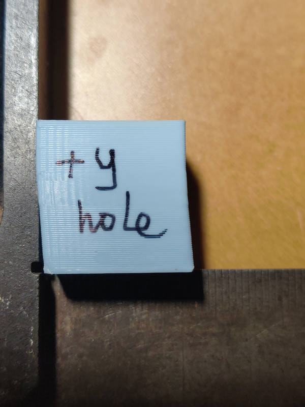
The cube is positioned with the -x face up, and the +y face to the left.
If I put the cutout on the y- face (or the x faces) the slope continues to the top.
The slicer has put the seam at the +x,+y corner, and the print path is anticlockwise, so y+ is the first perimeter of each layer to be printed. -
On further testing, the seam position doesn't seem to affect things - with the seam at the x0y+ corner, the cutout on the y+ face still makes the print vertical from the level of the cutout (as above).
I also compared 0.15 layers with 0.25 layers, and the slope looks exactly the same. Tried measuring the slope more precisely - seems to be about 1.4mm over 20mm, about 4deg. -
@Adrian52 can you post your config?
I also had a look at the changelog between beta2 and beta3, but I don't see any change that might cause your problem. Maybe have a look yourself: https://github.com/Duet3D/RepRapFirmware/wiki/Changelog-RRF-3.x-Beta#reprapfirmware-350beta3 -
@nikscha
This rabbit hole gets curioser and curioser.First, this is my config.g: as you see, I am using 2 orbiter extruders in tandem
; Think3DPrint3D configuration file for Mini Kossel for testing Duet WiFi

; Communication and general
M111 S0                             	; Debug off
M550 PKosselXL							; Machine name and Netbios name (can be anything you like)
M551 Preprap                        	; Machine password (used for FTP)
;*** If you have more than one Duet on your network, they must all have different MAC addresses, so change the last digits
;M540 P0xBE:0xEF:0xDE:0xAD:0xFE:0xED 	; MAC Address
;*** Wifi Networking
M552 S1									; Enable WiFi. Disabled for setup and testing. Enable once set up on your network.
M555 P0                           		; Set output to look like Reprap
M575 P1 B57600 S1						; Comms parameters for PanelDue
G21                                 	; Work in millimetres
G90                                		; Send absolute coordinates...
M83                                 	; ...but relative extruder moves

; Axis and motor configuration
M584 X0 Y1 Z2 E3:4						;explicitly assign drives
M569 P0 S0								; Drive 0 goes backwards - changed to backwards for robodigg clamps
M569 P1 S0								; Drive 1 goes backwards - "
M569 P2 S0								; Drive 2 goes backwards - "
M569 P3 S0								; Drive 3 goes backwards - changed for orbiter 1.5
M569 P4 S0								; Drive 4 goes backwards - orbiter 2.0
M84 S120								;set idle timeout to 120sec
;M574 X2 Y2 Z2 S1						; set endstop configuration (all endstops at high end, active high)
M574 X2 S1 P"xstop"
M574 Y2 S1 P"ystop"
M574 Z2 S1 P"zstop"
;*** The homed height is deliberately set too high in the following - you will adjust it during calibration
M665 L360.25 R173.990 H297.084 B120.0 X0.538 Y0.525 Z0.000
M666 X1.493 Y-1.213 Z-0.280 A-1.03 B-0.66		; put your endstop adjustments here, or let auto calibration find them
M579 X1.005 Y1.007 Z1.00		        	;correct x y z scaling
M350 X16 Y16 Z16 I1	    				; Set 16x microstepping with interpolation
M350 E16:16 I1								; Set exruder to 16x with interpolation
M92 X200 Y200 Z200						; Set axis steps/mm
M906 X1400 Y1400 Z1400 I0.6		; Set motor currents (mA) and increase idle current to 60%
M906 E850:850 I10							;current for orbiter
M201 X2800 Y2800 Z2800 E5000:5000			; Accelerations (mm/s^2)
M203 X20000 Y20000 Z20000 E7200:7200			; Maximum speeds (mm/min)
M566 X2100 Y2100 Z2100 E3000 P1			; Maximum instant speed changes mm/minute, switch on 2.03 jerk policy

; Thermistors and heaters

M308 S0 P"bedtemp" A"Bed temp" Y"thermistor" T100000 B4138      ; configure sensor 0 as thermistor on pin bedtemp
M950 H0 C"bedheat" T0                               ; create bed heater output on bedheat and map it to sensor 0
M307 H0 B0 S1.00                                    ; disable bang-bang mode for the nozzle heater and set PWM limit
M140 H0									;bed heater is heater 0
M143 H0 S125
M308 S1 P"e0temp" Y"thermistor" T100000 B4725 C7.060000e-8 A"Extruder temp"  ; configure sensor 1 as thermister via e0temp
M308 S2 P"e1temp" Y"thermistor" T100000 B4725 C7.060000e-8 A"Cold end temp"  ; configure sensor 2 as thermister via e1temp
;M308 S1 P"spi.cs1" Y"rtdmax31865" A"Extruder temp"  ; configure sensor 1 as thermocouple via CS pin spi.cs1
;M308 S2 P"spi.cs2" Y"rtdmax31865" A"Test temp"		; configure sensor 2
M950 H1 C"e0heat" T1                                ; create nozzle heater output on e0heat and map it to sensor 1
M950 P2 C"e1heat"									; create output to switch lights
M307 H1 B0 S1.00                                    ; disable bang-bang mode for the nozzle heater and set PWM limit
M143 H1 S300                                        ; set temperature limit for heater 1 to 295C
M570 H1 S60											;cancel print 60min after extruder temp fault

; ****Fans
M950 F0 C"fan0" Q500                               ; create fan 0 on pin fan0 and set its frequency
M106 P0 S0 H-1                                      ; set fan 0 value. Thermostatic control is turned off
M950 F1 C"fan1" Q2500                                ; create fan 1 on pin fan1 and set its frequency
M106 P1 S1 H1 T45                                   ; set fan 1 value. Thermostatic control is turned on
M950 F2 C"!Fan2+^exp.pb6" Q25000
M106 P2 S0 H-1 C"Extra cool"
; Tools
M563 P0 D0:1 H1 F0                                   ; define tool 0
G10 P0 X0 Y0 Z0                                     ; set tool 0 axis offsets
G10 P0 R0 S0                                        ; set initial tool 0 active and standby temperatures to 0C

; Tool definitions
;M563 P0 D0 H1 F0:2                     			; Define tool 0 with fan 0, fan 2 linked
;M563 P0 D0 H1 F0 									; tool 0 with fan 0 only
G10 P0 S0 R0                        				; Set tool 0 operating and standby temperatures
M567 P0 E1.00:1.00									; set mix ratio
M309 p0 S0.006										; set heater feed forward for tool 0
;*** If you have a single-nozzle build, comment the next 2 lines
;M563 P1 D1 H2                      					; Define tool 1
;G10 P1 S0 R0                       				; Set tool 1 operating and standby temperatures
;M92 E458                        					; Set extruder steps per mm
M92 E667:667                        					; Set extruder steps per mm orbiter
M572 D0:1 S0.04											;pressure advance extruder 0 and 1
;M572 D1 S0.02										; pressure advance extruder 1
M207 S2.1 R0.0 F7200 Z0.05             		; firmware retraction setting

; Z probe and compensation definition
M558 P8 C"zprobe.in+zprobe.mod" R0.4 F1000 H5 A2 S-1		;Z probe smart effector
M672 S105:20:235									;set z probe sensitivity
;G31 P100 X0 Y0 Z-0.10								;probe offset for old smart effector
G31 P100 X0 Y0 Z-0.02								;probe offset for new smart effector 0.27 for petg 0.18 for pla try 0.1 for direct drive

   												;laser filament monitor settings
M591 D0 P5 C"connlcd.encb" R01:300 E10 L0.398 S1 A1		;version for reprap3

;M955 P0 C"spi.cs3+spi.cs4" I64 S5000 R10							;accelerometer configuration

;*** If you are using axis compensation, put the figures in the following command
M556 S100 X0.05 Y0 Z0                  				; Axis compensation here
M593 P"ei3" F30 L400 S0.0							; Damp ringing at 30Hz
M376 H10											;taper mesh over 10mm
M501												;use override-config.g parameters
M208 S1 Z-0.2										; set minimum Z
M912 P0 S-2											;calibration mcu temperature reading
G28													;Home axes
M42 P2 S1											;lights on
;G29 S1												;load height map and activate mesh compensation
;M290 S-0.1											;current baby steps
;
T0													; select first hot end
I have made a couple more observations:
When printing 2 cubes together, the slope on each seems to be half that of a single cube. Similarly, printing a cube rotated 45deg, so that a corner is pointing in the y direction, the two +y direction faces are sloping with half the slope, but the -y direction faces are vertical.
As I had previously seen that a cutout on the y+ face of a cube made the print vertical from that point, I wondered if a tab on the y+ face might have the same effect. The answer is no - a 2x2x2 cube attached at the bottom middle of the y+ face results in half the slope seen with no cube. A 2x2x2 cutout in the same position gives a vertical cube.
-
A further note on versions - I just tried 3.5beta2+ (2023-02-10), and this gives no slope - a perfectly vertical cube.
-
@Adrian52 thanks for reporting this and for your investigations. We've created this issue https://github.com/Duet3D/RepRapFirmware/issues/924 and I will investigate it.
closed Potential issue with delta printers #924
Duet WiFi hardware designer and firmware engineer
Please do not ask me for Duet support via PM or email, use the forum
http://www.escher3d.com, https://miscsolutions.wordpress.com -
@dc42 Thank you. I just tried the 3.5rc1+ release from dropbox, and that still has the y slope.
Incidentally, the filament monitor output was still a little bit truncated:Duet3D laser filament monitor v2 on pin (connlcd.encb,connlcd.3), enabled when SD printing, allow 1% to 300%, check all extruding moves every 10.0mm, calibration factor 0.398, quality 224, brightness 30, shutter 123, measured min 99% avg 101% max 122% over -
@dc42 - Adrian mentioned using a delta, 3.4.0b3 had an issue with deltas that seems similar.
https://forum.duet3d.com/topic/25166/3-4-0-b3-leaning-prints?_=1698282891138 -
@Fred-Y I was getting a bit of deja vu, but had not checked back - thanks for the link.
-
 undefined Jimborr referenced this topic
-
The latest rc1+ (from 31/10/2023) seems to have solved the issue. Thank you.
-
@Adrian52 thanks for confirming. I'll mark this thread as solved, but feel free to change it to unsolved if the issue returns.
Duet WiFi hardware designer and firmware engineer
Please do not ask me for Duet support via PM or email, use the forum
http://www.escher3d.com, https://miscsolutions.wordpress.com -
 undefined dc42 marked this topic as a question
-
undefined dc42 has marked this topic as solved
-
undefined Adrian52 has marked this topic as unsolved
-
There seems to have been a change in the most recent prusa slicer(2.7.0alpha1) and orca slicer(1.8.0beta2) which has caused a recurrence of this problem.
A further note - trying to find the minimal conditions to trigger the slope, I found that a 20mm cube with no fill and no top layer does not slope, but the cube with fill (still no top) does slope. So presumably the problem lies in the transition to and/or from perimeter to infill. -
I too have observed a similar issue with the 3.5.0-rc1 firmware. For me, it happens when I print a cubioid in vase mode. Printing the same stl with two walls does not exhibit the problem. I reverted back to 3.4.6 and the prints are fine.
-
@Adrian52 If you now have a simple repeatable case I wonder if you could try changing a few things that look like possible problems to me....
- I think you are only setting the jerk value for one of your two extruders with this line:
M566 X2100 Y2100 Z2100 E3000 P1Can you try running M566 in the console to check what jerk settings you have for the two extruders (and maybe post the results). If they are not the same could you try setting both extruders to 3000 jerk. (so E3000:30000)
- Your jerk settings seem very high to me and I've seen that cause skipped steps. Could you try reducing them all to something like:
M566 X500 Y500 Z500 E500:500-
Can you try removing the L400 option from your input shaping command (not many folks will be setting that parameter and how it works has also changed in the most recent rc1 builds).
-
Can you try disabling input shaping completely.
It is probably best to try the changes individually though I suspect that item 1 is just wrong. However applying the "correct" jerk may have a knock on effect given that you are using the two extruders in tandem as I think that will now allow the very high jerk settings you have to be used (at the moment I think may be limited by the default jerk for extruder 1).
I understand that things worked fine in 3.4, but some of the changes in 3.5 (in particular some of the changes to IS) may mean that things like the high jerk settings are now causing problems that would not have been triggered in 3.4. I'm also not suggesting that for instance you run with IS disabled or that the suggested jerk values are the final ones, it it more a case of exploring possible causes.
Good Luck!
-
@gloomyandy Thanks for looking at the problem.
- the output from M566 is
22/11/2023, 14:21:15 	M566
Maximum jerk rates (mm/min): X: 2100.0, Y: 2100.0, Z: 2100.0, E: 3000.0:3000.0, jerk policy: 1
So that jerk command I have does seem to set both extruders.
- I will try a lower E jerk setting
- I played with the L parameter at DC42's suggestion, because with 3.5 I was getting very hesitant movement of the extruder, leaving lots of little loops on the print surface. This was the minimum value that gave fluent movement and a smooth surface.
- I should have mentioned that I have already disabled IS, and still get the y slope
Will report how lower jerk looks
-
@gloomyandy with E jerk at 500 for both extruders, I still get the y slope if the cube is 15% filled, but vertical sides if the cube has no fill. I checked this with the release version 1.8.0 of orca slicer.
-
@Adrian52 Did you experiment with lower jerk settings on X and Y? 2100 seems pretty high.
-
@gloomyandy not so far - can do. Didn't think they were that high for a delta.
-
@balajiramani hi - I just tried vase mode in orca slicer, and it printed vertically for me. I am using a recent 3.5rc1+ (from 2023-11-1), so that may be the difference .
