Duet3D Logo Duet3D
    • Tags
    • Documentation
    • Order
    • Register
    • Login
    1. Home
    2. gloomyandy
    • Profile
    • Following 0
    • Followers 8
    • Topics 10
    • Posts 1,634
    • Best 342
    • Controversial 1
    • Groups 0

    gloomyandy

    @gloomyandy

    460
    Reputation
    235
    Profile views
    1.6k
    Posts
    8
    Followers
    0
    Following
    Joined Last Online

    gloomyandy Unfollow Follow

    Best posts made by gloomyandy

    • Comparing klipper and RRF input shaper data collection

      Hi in another thread (https://forum.duet3d.com/topic/25931/input-shaping-testing-and-thoughts) I reported my progress with using input shaping to deal with some of the ringing on my printer. As a result of these tests I decided to take a closer look at how klipper and RRF collect resonance data to be used as the basis for analysis of ringing and to help a user configure input shaping. Hopefully this will provide some useful input to @DC42 and @mfs12 in the production of the RRF input shaper plugin.

      So both systems basically run some sort of movement to excite resonances in the printer and use an accelerometer to collect the data, In particular:

      • RRF performs a simple linear move at the maximum current movement speed and when that move stops it then collects typically 1000 samples (taking less than a second) which is about 46kBytes of data.
      • klipper runs what they call a resonance test that basically moves the print head from side to side a short distance ramping up the speed (and acceleration) of these movements to scan through a set of frequencies (the default range is 5 to 133Hz). This generates about 130 seconds worth of data, which is typically 170,000 samples, 3.6MBytes of data.

      To allow comparison of the two I created a script that generates a klipper style set of movements to allow me to record a set of sample use RRF.

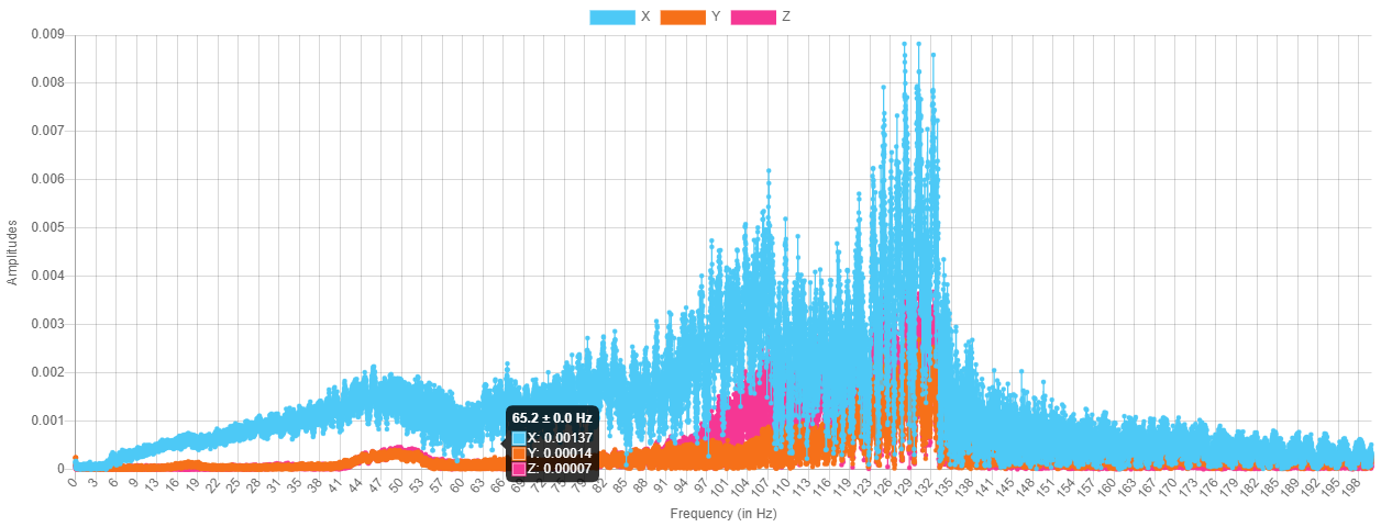
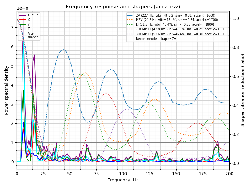
      I collected two sets of data on my CoreXY printer. The first graph shows the RRF FFT results:
      acc2.png
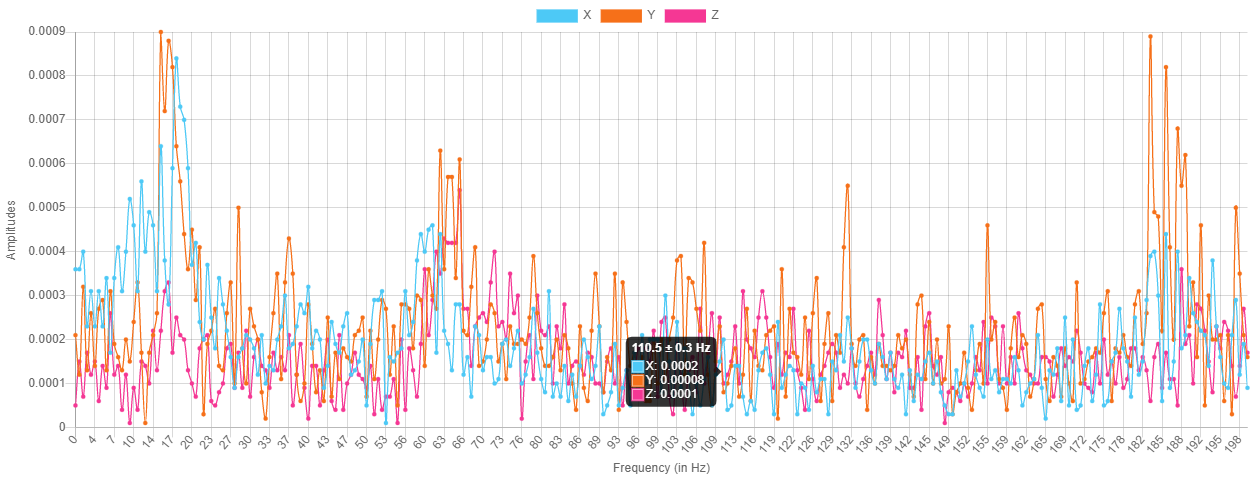
      The second is the klipper style data:
      acc4.png
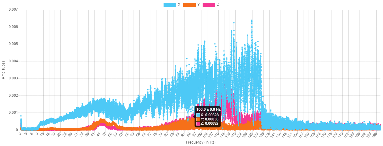
      As can be seen the give very different results!

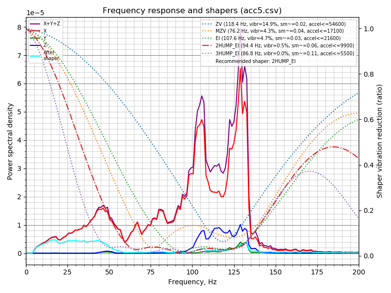
      I also modified the sample files to allow them to be processed by the klipper calibrate_shaper.py script. For the RRF style data it gave:
      acc2.png
      The klipper style data gives:
      acc4.png

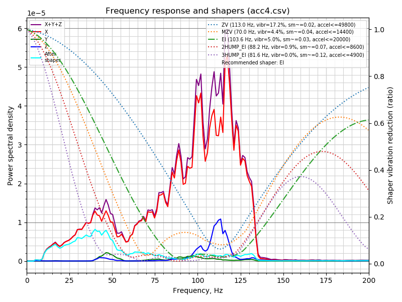
      With such different outcomes it is hard to really decide which is correct. I've not tested the recommendation based on the klipper style data (RRF does not currently support the ei shaper). However based on my previous tests (and on measuring the ringing on the prints), the main visible problem is the hump that can be seen around 40Hz on the klipper style data. Some further thoughts and comments....

      • Looking at the raw samples the current RRF data set only has a very small number of actual "real" values, in the file shown here only the first 100 points are above the noise floor. I'm not sure if this is really enough data to allow for an accurate analysis of what is happening over the given frequency range.
      • The current input shaper plugin performs the test using the maximum movement speed, in my case this was 200mm/s. I'm not sure that this is a good idea. On my machine this introduces a considerable amount of energy into the frame of the printer such that it rocks. I'm pretty sure that this is responsible for the very low frequency peaks shown in the output. Reducing the maximum speed gives a different output (with not such a large low frequency peak), but has even fewer samples above the noise.
      • To check that the "klipper" data was working correctly I monitored the test using a "spectrum analyser" app on my phone and it did indeed show a rising frequency from around 5Hz to 133Hz. So I think it is working correctly.
      • To allow me to collect the larger volume of data needed for the klipper runs I had to modify RRF (in this case the STM32 port) to allow more than 64K of samples and also to fix an overflow problem in the data rate calculation when there are a large number of samples being saved.

      I will continue to investigate this a little further, but I thought this data might be of interest and I'd welcome any thoughts or feedback.

      posted in Beta Firmware
      gloomyandyundefined
      gloomyandy
    • RE: Comparing klipper and RRF input shaper data collection

      A quick update. In a previous post I mentioned

      There is something a little odd going off with the generated gcode, it does not run for as long as I would expect (approx 130 seconds). I'm not totally sure why, it could be because at the higher frequencies the movement is very small. It may be that jerk has some impact. I'm not sure if this problem is due to my script or the original klipper code.

      Jerk does indeed have some impact but that was not the major problem. After running various additional tests and trying to figure out what was going on I reached out to @dc42 and he spotted that the moves being used by this test are not printing moves (as they do not include any extrusion), but I was setting the acceleration for a printing move using M204 P<aaaa>. I have now corrected this by specifying both P and T (just in case!), in the M204 commands. With this change the gcode file now runs for the correct period. Many thanks for your help David!

      This has made a small change to the collected data as shown below:
      acc5.png
      and the data as processed by klipper:
      acc5.png

      The updated script (which also includes some other small corrections) is:

      var title = "Klipper style vibration test V0.3"
      var axis="Y"
      var datarate=1320
      var stime = state.upTime
      var min_freq = 5.0
      var max_freq = 10000/75
      var accel_per_hz = 75
      var hz_per_sec = 1
      var freq = var.min_freq
      var max_accel = var.max_freq * var.accel_per_hz
      var X = 150.0
      var Y = 150.0
      var sign = 1.0
      var t_seg = 0
      var accel = 0
      var max_v = 0
      var L = 0
      var nX = 0
      var old_freq = 0
      var filename = "/gcodes/vtest_" ^ var.axis ^ ".gcode"
      echo "max_accel " ^ var.max_accel ^ " min freq " ^ var.min_freq ^ " max freq " ^ var.max_freq
      echo > var.filename " "
      echo >>var.filename "M201 X" ^ var.max_accel ^ " Y" ^ var.max_accel
      echo >>var.filename "M205 X0 Y0"
      echo >>var.filename "G91"
      echo >>var.filename "M400"
      echo >>var.filename "G4 S1"
      echo >>var.filename "M956 P0 A0 S" ^ (var.max_freq - var.min_freq) * var.datarate * var.hz_per_sec 
      
      echo "Testing " ^ floor(var.freq)
      echo >> var.filename "echo " ^ var.freq
      while var.freq < var.max_freq + 0.000001
      	set var.t_seg = 0.25 / var.freq
      	set var.accel = var.accel_per_hz * var.freq
      	set var.max_v = var.accel * var.t_seg
      	echo >>var.filename "M204 P" ^ var.accel ^ " T" ^ var.accel
      	set var.L = 0.5 * var.accel * (var.t_seg*var.t_seg)
      	set var.nX = (var.sign * var.L)
      	echo >>var.filename "G1 " ^ var.axis ^ var.nX ^ " F" ^ var.max_v*60
      	echo >>var.filename "G1 " ^ var.axis ^ -var.nX
      	set var.sign = -var.sign
      	set var.old_freq = var.freq
      	set var.freq = var.freq + (2. * var.t_seg * var.hz_per_sec)
      	if floor(var.freq) > floor(var.old_freq)
      		;echo >> var.filename "echo " ^ floor(var.freq)
      		echo "Testing " ^ floor(var.freq)
      echo >>var.filename "G90"	
      echo "total time " ^ state.upTime - var.stime
      
      posted in Beta Firmware
      gloomyandyundefined
      gloomyandy
    • RE: The most helpful post you'll read today

      From the M671 documentation....

      The X and Y coordinates in M671 are measured from the origin X0,Y0 set by M208. Measure to the pivot
      point of the bed where it connects to the Z axis. This is often each leadscrew, but may also be offset from
      the leadscrew if the bed rests on a carriage extending out from the leadscrew.
      
      posted in General Discussion
      gloomyandyundefined
      gloomyandy
    • RE: Comparing klipper and RRF input shaper data collection

      @mfs12 Here is the script. It is pretty much a simple translation of the klipper code. A few notes:

      • I originally hoped to just have it drive the printer, but the script was too slow (at least in SBC mode), so instead it generates a gcode file that you then need to print.
      • I modified it to use relative coordinates so that you can just position the print head before you run the script.
      • There is something a little odd going off with the generated gcode, it does not run for as long as I would expect (approx 130 seconds). I'm not totally sure why, it could be because at the higher frequencies the movement is very small. It may be that jerk has some impact. I'm not sure if this problem is due to my script or the original klipper code.
      • If you want to use it to collect acceleration data you will need a modified version of RRF that allows more than 64K samples to be collected and that fixes the overflow bug in the data rate calculation.
      • Use it with care, and be ready to hit emergency stop!
      var title = "Klipper style vibration test V0.2"
      var axis="X"
      var datarate=1320
      var stime = state.upTime
      var min_freq = 5.0
      var max_freq = 10000/75
      var accel_per_hz = 75
      var hz_per_sec = 1
      var freq = var.min_freq
      var max_accel = var.max_freq * var.accel_per_hz
      var X = 150.0
      var Y = 150.0
      var sign = 1.0
      var t_seg = 0
      var accel = 0
      var max_v = 0
      var L = 0
      var nX = 0
      var old_freq = 0
      echo "max_accel " ^ var.max_accel ^ " min freq " ^ var.min_freq ^ " max freq " ^ var.max_freq
      echo > "/gcodes/vtest.gcode" " "
      ;echo >>"/gcodes/vtest.gcode" "G1 X" ^ var.X ^ " Y" ^ var.Y
      echo >>"/gcodes/vtest.gcode" "M201 X" ^ var.max_accel ^ " Y" ^ var.max_accel
      echo >>"/gcodes/vtest.gcode" "G91"
      echo >>"/gcodes/vtest.gcode" "M400"
      echo >>"/gcodes/vtest.gcode" "G4 S1"
      echo >>"/gcodes/vtest.gcode" "M956 P0 A0 S" ^ (var.max_freq - var.min_freq) * var.datarate * var.hz_per_sec 
      
      ;G1 X{var.X} Y{var.Y}
      echo "Testing " ^ var.freq
      while var.freq < var.max_freq + 0.000001
      	set var.t_seg = 0.25 / var.freq
      	set var.accel = var.accel_per_hz * var.freq
      	set var.max_v = var.accel * var.t_seg
      	;echo >>"/jobs/vtest.gcode" "M204 P" ^ {var.accel}
      	echo >>"/gcodes/vtest.gcode" "M204 P" ^ var.accel
      	set var.L = 0.5 * var.accel * (var.t_seg*var.t_seg)
      	set var.nX = (var.sign * var.L)
      	;echo "freq " ^ var.freq ^ " t_seg " ^ var.t_seg ^ " accel " ^ var.accel ^ " max_v " ^ var.max_v ^ " L " ^ var.L ^ " nX " ^ var.nX ^ " {nX} " ^ {var.nX}
      	;echo >>"vtest.gcode" "G1 X" ^ {var.nX} ^ " F" ^ {var.max_v*60}
      	echo >>"/gcodes/vtest.gcode" "G1 X" ^ var.nX ^ " F" ^ var.max_v*60
      	echo >>"/gcodes/vtest.gcode" "G1 X" ^ -var.nX
      	set var.sign = -var.sign
      	set var.old_freq = var.freq
      	set var.freq = var.freq + (2. * var.t_seg * var.hz_per_sec)
      	if floor(var.freq) > floor(var.old_freq)
      		echo "Testing " ^ var.freq 
      echo >>"/gcodes/vtest.gcode" "G90"	
      echo "total time " ^ state.upTime - var.stime
      
      posted in Beta Firmware
      gloomyandyundefined
      gloomyandy
    • RE: Heater fault on heated bed because it's rising to slow.

      @pfn There are quite a few fixes post beta6: https://github.com/Duet3D/RepRapFirmware/commits/3.4-dev

      Some of these may impact the problem you are seeing...
      https://github.com/Duet3D/RepRapFirmware/commit/37b4e02726993763b477181b6aa918089e2210b4
      https://github.com/Duet3D/RepRapFirmware/commit/1e0e6c99252dee6aa20194f212aca3be6e68415a

      0 dc42 committed to Duet3D/RepRapFirmware
      Fixed heater fault detection while heating up
      
      Also shortened the M307 response so that it fits in the reply buffer
      0 dc42 committed to Duet3D/RepRapFirmware
      Fixed bug in calculation of heater PID parameters
      posted in Tuning and tweaking
      gloomyandyundefined
      gloomyandy
    • RE: Beta testers for multiple motion system support

      @o_lampe It looks like the code for this will be on the 3.5-dev repo. I will at some point be picking that code up and providing an STM32 version, so hopefully we will be able to contribute to the testing of this new feature. I usually try to track new developments reasonably closely so hopefully it will be possible to do that again.

      posted in Beta Firmware
      gloomyandyundefined
      gloomyandy
    • RE: Pressure Advance smooth time

      @Kiolia You may want to keep any eye on these two threads:
      https://klipper.discourse.group/t/modification-of-pressure-advance-for-high-speed-bowden-printers/13053/13
      https://klipper.discourse.group/t/pressure-advance-smooth-time-skews-pressure-advance/13451

      It would seem that the jury is still out on PA smoothing at higher speeds....

      posted in Firmware wishlist
      gloomyandyundefined
      gloomyandy
    • RE: What’s the stance on RRF on none Duet boards?

      @dc42 There is a further 32K that is used for NVM emulation to hold the stack/registers after a reset. This is rather wasteful but on the chips we currently support not really an issue.

      Some other things are also a little different in that we have additional code to support any mixture of TMC2208/2209/5160 drivers. A software based UART (for TMC drivers) and software SPI. I'm also pretty sure that our CoreN2G has rahter more in it than strictly needed.

      posted in General Discussion
      gloomyandyundefined
      gloomyandy
    • RE: Missing Steps - Cant Print SpreadCycle StealthChop tuning help

      @droftarts As a further data point I use E3D 0.9 steppers with both TM2209 and TMC5160 drivers on a coreXY setup. In both cases I'd say that although they work for me, they are certainly much noisier than the 1.8 motors they replaced and it was also much harder to get sensorless homing configured with them, the range of settings in which the motor would actually move but would also stall when needed seemed to be much smaller.

      I operate the drives in Stealthchop all of the time at relatively modest speeds. Print speed max 60mm/S non print moves max 200mm/S. I'm running lower steps/mm than those quoted here mine are 180steps/mm.

      All of the above testing was using the RRF STM32F4 port on a Bigtreetech SKR Pro.

      posted in Tuning and tweaking
      gloomyandyundefined
      gloomyandy
    • RE: RepRapFirmware 3.3beta1 now available

      @Toastinator Probably best to follow DC42's request and create a new thread for your problem.

      posted in Beta Firmware
      gloomyandyundefined
      gloomyandy

    Latest posts made by gloomyandy

    • RE: Error: Expansion board 119 stopped sending status (3.6.0-rc.2)

      @jumpedwithbothfeet If this happened today (the 14th) then the crash in your board 119 log is probably nothing to do with it (as that happened yesterday the 13th). That may have been caused by a static problem, but it is hard to be sure. The board 119 log seems to show that it had been running for almost eight hours when you produced the m122 log. I guess the question is did this happen today or yesterday (which it may not now be possible to establish)? If it happens again make a note of the times. Do you know when you started the print? If that was before 21:00 on the 13th, then it may well be that the crash then caused the CAN-FD problems.

      posted in Beta Firmware
      gloomyandyundefined
      gloomyandy
    • RE: Error: Expansion board 119 stopped sending status (3.6.0-rc.2)

      @jumpedwithbothfeet Was the M122 report from board 119 taken without needing to do any sort of reset? The M122 for board 119 is showing a possible crash at 2025-05-13 21:03 how does that date/time relate to when you had the stopped sending status message? As mentioned above I'd suspect some sort of wiring problem (which may have possibly caused the previously reported crash?), but it is hard to be sure. Has the printer been working ok previously?

      posted in Beta Firmware
      gloomyandyundefined
      gloomyandy
    • RE: Z-Probe (Klicky) frequently not triggered

      @effnish Have you tried reverting to 3.5.4 and retesting? If not I think it would be worth doing that. This would confirm that the problem is not some sort of hardware problem.

      posted in Beta Firmware
      gloomyandyundefined
      gloomyandy
    • RE: Struggling with PID tuning on Duet 3 with custom CoreXY

      @aria_james It would probably help if you could post a screenshot showing the sort of temperature variation you are seeing during a print.

      posted in Duet Hardware and wiring
      gloomyandyundefined
      gloomyandy
    • RE: Duet 3 mini 5+ vs Prusa Mk4

      @handyandy I suspect it will be as good as you are prepared to calibrate it. The thing is that Prusa will have probably thousands of hours of calibration tests and data all on the same hardware and will have had a lot of engineers analysing that data and tuning the firmware to get the best out of the hardware. You have a single example of your hardware and just you to calibrate and tune it...

      posted in Tuning and tweaking
      gloomyandyundefined
      gloomyandy
    • RE: [3.6.0-rc2] Error: G30: Z probe readings not consistent

      @caviara Are you seeing this movement show up in the X/Y position displayed by DWC?

      posted in Beta Firmware
      gloomyandyundefined
      gloomyandy
    • RE: [3.6.0-rc.2] changed behaviour while homing on coreXY

      @marvineer What exactly are you seeing happen? As reported by dc42 he sees an initial diagonal move followed by a Y direction move for the homing move. Is that different to what you are seeing? Perhaps if you post a video of what you are seeing that will help? My understanding is that you should see what dc42 has reported and that is the expected movement.

      posted in Beta Firmware
      gloomyandyundefined
      gloomyandy
    • RE: Duet SZP reconnect

      @vaike_peeter I would not expect re-initialising the probe to cause the board to reset, but it looks like there was a "HardFault" reset in your M122 output. One for @dc42 to comment on I think.

      posted in Duet Hardware and wiring
      gloomyandyundefined
      gloomyandy
    • RE: Duet SZP reconnect

      @vaike_peeter Can you post the M558 command you were using before and the one you are using now so we can understand what the problem was?

      posted in Duet Hardware and wiring
      gloomyandyundefined
      gloomyandy
    • RE: SZP mounting

      @droftarts Just to be clear, the key thing to test for touch probing is....

      1. With the nozzle in contact with the bed. Determine a coil current that gives good readings (probably using the auto calibration process).
      2. Now raise the probe and see at what height above the bed you no longer get valid readings. A value slightly lower than this is in effect the maximum dive height you can use for touch probing.

      From what I've seen the closer the coil is mounted to the nozzle tip the narrower is the working range of the coil (and hence the dive height for touch probing is closer to the bed).

      The tricky part is that you need to get the probe to within that dive height. At the moment the best way seems to be to use the two stage process described above. However the problem is that the first stage relies on you manually calibrating a trigger point that works reliably and that gets you within that dive height. The closer the dive height is to the bed the more likely it is that issues like temperature drift are going to cause problems and possibly a crash into the bed. Heating the nozzle (to allow more accurate touch probing even with plastic on the nozzle), may make it more likely that you get temperature drift in this first stage.

      I'm not sure but I don't think dc42 has been testing with the full two stage process, I think he has been using the switch probe on his toolchanger for initial Z homing and then just testing the homing touch homing operation (that's also how I ran a lot of my tests). I think we still need to gather more data on the best compromise.

      Note that there is a possible alternate stage 1 homing process. This is to basically set things up with the drive current needed for touch homing and then to simply keep lowering the probe say 1mm at a time and then check to see if the probe has started to return valid readings yet. This should bring the probe to a point that it can now be used for touch probing. We don't currently have any way to actually trigger the probe based on a change from invalid to valid reading, but it may be something to consider. If it turns out that temperature drift for initial probing is a problem it may be that a 3 stage sequence would be best. Use normal threshold homing to get to a point say 6mm above the bed, then switch drive current and drop 1mm at a time until we start to get valid probe readings.

      Finally you probably want to start the touch probe operation as close to bed as possible. This is because any "rough spots" in the Z motion system can cause a false touch trigger, which will require an increase in the touch threshold to avoid. This in turn results in a higher force touch, which is more likely to cause damage.

      posted in Duet Hardware and wiring
      gloomyandyundefined
      gloomyandy