Duet3D Logo Duet3D
    • Tags
    • Documentation
    • Order
    • Register
    • Login
    1. Home
    2. Adrian52
    • Profile
    • Following 0
    • Followers 1
    • Topics 18
    • Posts 252
    • Best 37
    • Controversial 0
    • Groups 0

    Adrian52

    @Adrian52

    50
    Reputation
    33
    Profile views
    252
    Posts
    1
    Followers
    0
    Following
    Joined Last Online

    Adrian52 Unfollow Follow

    Best posts made by Adrian52

    • RE: [feature] Adaptive / Feedforward Temperature setpoint

      I am finding this feature really interesting. For pla and a 0.4 nozzle, I find
      M309 p0 S0.06 T6 A40
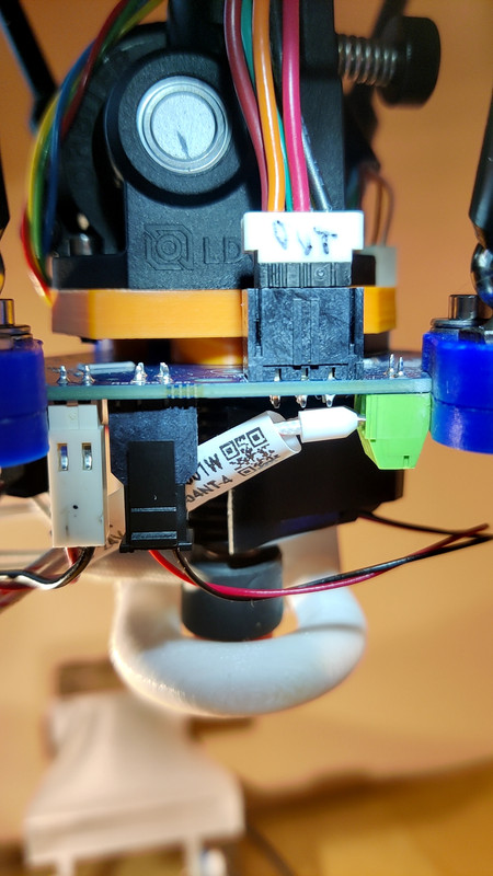
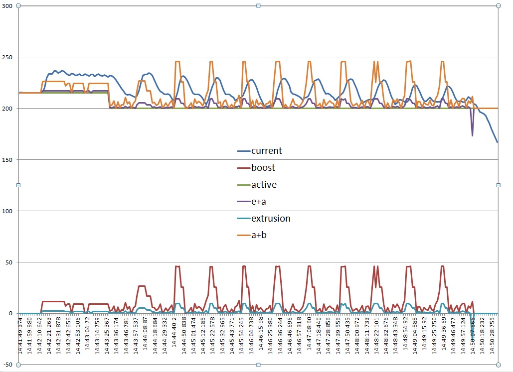
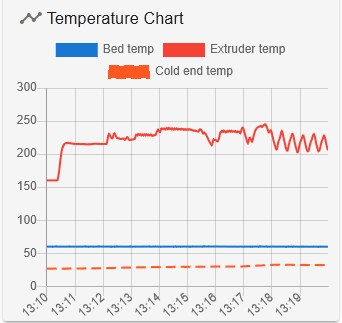
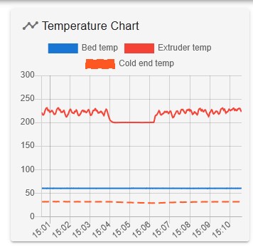
      works ok. I use a base temperature of 200, and first layer temperature of 215. First layer prints at 220-225, as I use 20mmsec for perimeter and 40mm/sec for infill. Using a revo 40watt heater and revo cht nozzle, temperatures change quite quickly (low thermal mass). Experimenting with higher speeds, inner perimeters and infill print fine at 140mm/sec (DWC reports about 22cumm/sec) - accurate weighing of resulting print showed that there was no under extrusion. I am not currently using non-linear extrusion. I have a single nozzle delta, so sometimes change filament mid print to get a multicolour effect. The adaptive feed forward is good for this as the base temperature is high enough to load and prime the new filament, but there is little oozing so you get a clean change. This is what a manual filament change looks like
      alt text

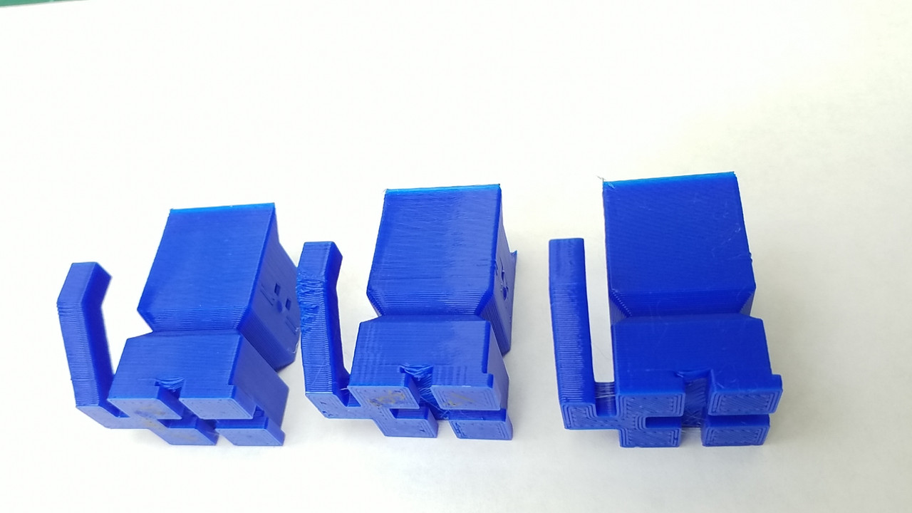
      The print quality with adaptive feed forward seems excellent, and still finding the limits of how fast one can go.

      posted in Firmware developers
      Adrian52undefined
      Adrian52
    • RE: Indirect (bearing) laser filament monitor concept

      @3dmntbighker I have put a new version on thingiverse, 3649565. I have increased the play, and made the bolts screw in from the side. This is easy for the bottom bearing, but you need a 7mm bolt for the upper bearing to fit between the vertical bolts. Their spacing is determined by the holes on the PCB.

      I have done more experiments with the gap between sensor and top bearing, and have concluded so far that a 5mm spacer is probably ok. I realised that my initial results were essentially single points for the max and min - with repeated runs, the picture is not so clear, but I think 5mm is better than no spacer.

      The percentages I get are still high, but quite reproducible - for the 5mm spacer, the average is about 270%, with the min not below 259, and the max not above 287 on 4 runs of at least 500mm extrusion. The relationship between sensor distance and average percentage reported is very linear - I have 12 points in my dataset now, with a least squares linear fit r squared of 0.998. The slope is 23.0 - the average percentage increases by 23 for each mm of gap between the sensor and bearing surface.

      posted in Filament Monitor
      Adrian52undefined
      Adrian52
    • RE: Orbiter 2 extruder mounting for Smart effector with Magball arms

      @fred-y Thanks for this idea - it seems to work. I made this:
      alt text
      using the two holes on the motor side of the extruder. This leaves a nice gap on the molex connector side for the plug to fit properly.
      This is how it looks in situ:
      alt text

      I am using the default sensitivity on a v3 smart effector, and found that it needed an extra -0.04 on the probe offset. Seems to work well though - a 19 point G32 gave a 0.010 fit.

      The mount pictured was printed with the new setup - I was fine tuning the thread diameter - 12.3mm was good for me. I havent pushed the new setup yet - seems promising though.

      posted in Smart effector for delta printers
      Adrian52undefined
      Adrian52
    • RE: Overhangs

      @jay_s_uk I find the easiest thing is to set a minimum layer time. The cat on the left is 20sec minimum, and the middle one is 10sec minimum. To check that its the time not speed of printing, the one on the right is one of two printed together with 20sec minimum.
      alt text

      posted in Tuning and tweaking
      Adrian52undefined
      Adrian52
    • RE: Indirect (bearing) laser filament monitor concept

      Have done a test print of the 693zz version in pla. alt text
      As you can see, the jaw tends to drop somewhat when the filament goes through. Do you think it needs some extra support? - maybe a plate that goes on the bottom? Or perhaps it would be better in petg? For my printing, I think the 4mm slots for the bearings could do with a tiny bit more tolerance. Great idea though - I am about to order a laser monitor on the strength of it.

      posted in Filament Monitor
      Adrian52undefined
      Adrian52
    • Orbiter 2 extruder mounting for Smart effector with Magball arms

      I have posted a design on thingiverse for mounting an Orbiter 2 extruder on the Smart effector. (https://www.thingiverse.com/thing:5239585)
      The magballs are moved out by 12mm, but maintaining the 55mm arm separation so you don't need to alter the carriages. This is enough to give access to the whole 250mm bed of my kossel XL with the extruder mounted horizontally just above the hotend. A prototype in pla seems to work fine, with a 19 point G32 giving mean deviation around 0.02. Print quality seems really good, although still optimising (still using my old input shaping settings). Have now printed it in carbon fibre petg, which should be stiffer, but not sure if that is necessary.
      Enjoy.

      posted in Smart effector for delta printers
      Adrian52undefined
      Adrian52
    • RE: Indirect (bearing) laser filament monitor concept

      Those changes seem to work OK
      alt text
      I used 0.1mm gap on each side of the bearings, and added 1mm to the base of the jaw to make the spring stronger. I didn't have room for washers, but the bearings rotate quite freely.

      posted in Filament Monitor
      Adrian52undefined
      Adrian52
    • RE: Indirect (bearing) laser filament monitor concept

      @3dmntbighker I have just put the files on thingiverse, 3618968

      posted in Filament Monitor
      Adrian52undefined
      Adrian52
    • RE: Indirect (bearing) laser filament monitor concept

      I have some preliminary results on the effect of changing the working distance of the sensor. The sensor Web page suggests 5 - 60mm for glossy surfaces, and 20-40mm for white paper. I printed some spacers to go between the top and middle sections of the indirect sensor, and checked the results after printing about 700mm of filament. I have been using A0, and 5mm measuring interval. With no spacer I got 72%(48), 149%(100), 243%(163) for min, average and maximum, normalised to average =100 in the brackets. With the 10mm spacer, I got 180(49), 370(100), 390(105). With a 15mm spacer, it was 472(97), 487(100), 505(103), and the 25mm spacer 575(81), 708(100), 749(106). I need to do more tests, but it looks like a longer working distance may be better - the 15mm spacer result is quite good. Perhaps this is worth investigating with direct sensing too.
      I am still getting the sensor reported as v1 after sending M591 D0 A0, sometimes reverting to v2 after a number of M591 D0 s (it is a v2 sensor)

      posted in Filament Monitor
      Adrian52undefined
      Adrian52
    • RE: Indirect (bearing) laser filament monitor concept

      @dc42 have done some more tests using a 20x20x4mm cube with 100%fill, printed at 60mm /sec, then varying the layer height or width to achieve specific filament movement rates. I print the first layer at 10mm/sec, so checking after 100 mm gives a 'slow' baseline for each test, and the total is a little over 700mm. Under these conditions I have no hiccups or missed steps.
      For me, the monitor works well with filament movements up to 1.3mm/sec (max/min within 10% of the average) , but for 1.5mm/sec and 2mm/sec, the max/min range becomes very wide, often going negative on the min side. I get similar results with and without a 5mm spacer, although the actual numbers are higher with the spacer as previously observed.
      The total extrusion reported by the monitor is very close (usually within 1%) to that shown by dwc or the slicer, even when the extrusion rate is above 1.5mm /sec.
      I have also started to note the error rates for the monitor reported by M122. For tests below 1.3mm/sec, frame errors are 2000-4000, and pol errors high(20000-30000). Above 1.3mm/sec, frame errors are 20000 - 30000, but pol errors are below 10000. I have also noticed that the error count is not zeroed when you start a new print - I have been doing a reset after each test to zero things up.

      posted in Filament Monitor
      Adrian52undefined
      Adrian52

    Latest posts made by Adrian52

    • RE: [feature] Adaptive / Feedforward Temperature setpoint

      @dc42 could the 6 second delay work in principle, if one wanted to go down that route?

      posted in Firmware developers
      Adrian52undefined
      Adrian52
    • RE: [feature] Adaptive / Feedforward Temperature setpoint

      @dc42 Have been wondering if a post process would be possible, and came across this article
      https://www.nature.com/articles/s41467-025-56140-1#MOESM1
      A rather impeccable source - maybe this is the way things might develop.

      posted in Firmware developers
      Adrian52undefined
      Adrian52
    • RE: [feature] Adaptive / Feedforward Temperature setpoint

      @dc42 the 60w heater on the revo seems to work fine, albeit with a tendency to overshoot a bit. The heat /cool curve (current) is not too bad, but lags the extrusion /boost curves by about 6 seconds. I tried increasing the queue size to 120, which is probably near the limit for my old duet2wifi. The A parameter at 50 works then. Is there any way to adjust for the lag?

      posted in Firmware developers
      Adrian52undefined
      Adrian52
    • RE: [feature] Adaptive / Feedforward Temperature setpoint

      Another experiment, with a 60W e3d revo heater, and no socks. The print is a 20x100mm cube, and a set of 6 8mm diameter cylinders. The cylinders print quite slowly and the cube at 140mm/sec.
      alt text
      This is an excel graph of csv data captured by btncmd (not worked out how to plot calculated values in btncmd).
      I added the active temp to the boost (a+b) to compare to the actual temp(current). You can see there is a bit of a lag on both the heating and cooling phases.
      I also plot the extrusion volume, and you can see that the boost anticipates the increase in extrusion, although not by enough to align with the current temperature. I plotted extrusion+active temp(e+a) to move the extrusion line up to the area of the current temp line.
      Not quite sure why the active +boost is below the current temperature in the initial phase - this is the relatively slow printing of the first layer.

      posted in Firmware developers
      Adrian52undefined
      Adrian52
    • RE: [feature] Adaptive / Feedforward Temperature setpoint

      @dc42 I am in fact using a revo micro on my delta, and just ordered a 60w heater, to see if it shortens the heating time. Hope it doesn't melt my part cooling duct!

      posted in Firmware developers
      Adrian52undefined
      Adrian52
    • RE: [feature] Adaptive / Feedforward Temperature setpoint

      @Triet Indeed - I was just looking at the feasibility of leaving off the sock. I was concerned that it would make temperature control unstable, but this doesn't seem to be the case. I thought a next step would be to plot the boosted temperature against the actual temperature, but waiting for an update that has the boosted temperature in the OM. On a learning curve with btncmd too - not used it before. Will aim to do a more formal comparison, including maximum speed and print quality.

      posted in Firmware developers
      Adrian52undefined
      Adrian52
    • RE: [feature] Adaptive / Feedforward Temperature setpoint

      To see if I could get the hotend to follow the forward temperature more closely, I tried removing the silicone sock from the revo heater, to see if I could get faster cooling. I redid the pid tune without the sock, and this is the plot printing a 100mmx20mm cube that has three small cylinders attached to one end. The cube walls print at 140mm/sec, and the cylinders around 20mm/sec. The cube has no fill or top, but the initial part shows printing the bottom infill
      alt text

      It then cycles between the fast cube walls and the slow cylinder walls. I was suprised how well controlled the temperature is under these conditions. The print weighed exactly the amount predicted by the slicer, so no underextrusion. The cube walls were printing at 22cumm/sec (o.4 nozzle, 0.2layers). The S parameter was set to 1

      Would be interesting to plot the feed forward boosted temperature on the temperature chart - is this possible?

      posted in Firmware developers
      Adrian52undefined
      Adrian52
    • RE: [feature] Adaptive / Feedforward Temperature setpoint

      @dc42 On my system, the highest A value that works is 48

      posted in Firmware developers
      Adrian52undefined
      Adrian52
    • RE: [feature] Adaptive / Feedforward Temperature setpoint

      @Triet I guess if one is using the feedforward in the way intended, the temperature shown is the target temperature. I have been playing with the parameters, trying to understand how they work. I am trying out a 0.25mm nozzle, which has an extrusion rate of about 8.8cumm/sec with 0.125mm layers at 140mm/sec, which is think corresponds to about 3.6mm/sec for 1.75 filament. A T parameter of 12 seems to give the expected increase of just greater than 40deg over the base temperature. I think there is a bit of under extrusion at this speed with the 0.25 nozzle, but checking that out. For my standard 0.4 cht nozzle, 0.2 layers give about 22cumm/sec at 140 mm/sec, that is about 9mm/sec filament. Using T5, this gives the expected increase of about 45deg above base temperature. I dont think the cht nozzle is underextruding under these conditions. I have just started using an S parameter of 1.0, and this seems to work fine with the 0.25 nozzle - not tried with the 0.4 nozzle yet. Tried increasing the A parameter to 50, and the feed forward stops working.
      I have been using M570 H1 P15 T45, and not been getting heater faults. The revo nozzle setup I am using has a low thermal mass, and seems to be controlled very well by the duet.

      posted in Firmware developers
      Adrian52undefined
      Adrian52
    • RE: Laser filament monitor frame errors with 3.6rc1 but not 3.6beta4

      @dc42 Thank you - that seems to have fixed it. Here is an M122 if you want to check anything. Did not notice anything untoward during this print.

      07/03/2025, 13:51:42 	m122
      === Diagnostics ===
      RepRapFirmware for Duet 2 WiFi/Ethernet version 3.6.0-rc.1+1 (2025-03-07 09:35:55) running on Duet WiFi 1.0 or 1.01
      Board ID: 08DAM-999TL-MQ4SD-6J9FD-3SJ6J-K593W
      Used output buffers: 1 of 26 (19 max)
      === RTOS ===
      Static ram: 24016
      Dynamic ram: 68004 of which 12 recycled
      Never used RAM 9244, free system stack 108 words
      Tasks: NETWORK(1,ready,17.5%,181) LASER(5,nWait 6,1.5%,214) HEAT(3,nWait 5,0.1%,313) Move(4,nWait 5,5.7%,243) MAIN(1,running,75.1%,836) IDLE(0,ready,0.1%,29), total 100.0%
      Owned mutexes:
      === Platform ===
      Last reset 00:45:51 ago, cause: software
      Last software reset at 2025-02-28 19:38, reason: User, Gcodes spinning, available RAM 25988, slot 2
      Software reset code 0x0003 HFSR 0x00000000 CFSR 0x00000000 ICSR 0x00400000 BFAR 0xe000ed38 SP 0x00000000 Task MAIN Freestk 0 n/a
      === Storage ===
      Free file entries: 10
      SD card 0 detected, interface speed: 20.0MBytes/sec
      SD card longest read time 12.6ms, write time 7.4ms, max retries 0
      === Move ===
      Segments created 780, maxWait 121347ms, bed comp in use: none, height map offset 0.000, hiccups added 0/45 (1.43ms), max steps late 1, ebfmin 0.00, ebfmax 0.00
      Pos req/act/dcf: 104132.00/104132/0.00 104132.00/104132/-0.00 104132.00/104132/0.00
      No step interrupt scheduled
      Driver 0: standstill, SG min 0
      Driver 1: standstill, SG min 0
      Driver 2: standstill, SG min 0
      Driver 3: standstill, SG min 0
      Driver 4: standstill, SG min 0
      Driver 5: 
      Driver 6: 
      Driver 7: 
      Driver 8: 
      Driver 9: 
      Driver 10: 
      Driver 11: 
      === DDARing 0 ===
      Scheduled moves 327303, completed 327303, LaErrors 0, Underruns [0, 0, 0]
      Segments left 0
      Code queue is empty
      === Heat ===
      Bed heaters 0 -1 -1 -1, chamber heaters -1 -1 -1 -1, ordering errs 0
      === GCodes ===
      Movement locks held by null
      HTTP is idle in state(s) 0
      Telnet is idle in state(s) 0
      File is idle in state(s) 0
      USB is idle in state(s) 0
      Aux is idle in state(s) 0
      Trigger is idle in state(s) 0
      Queue is idle in state(s) 0
      LCD is idle in state(s) 0
      Daemon is idle in state(s) 0
      Autopause is idle in state(s) 0
      === Filament sensors ===
      Driver 11: pos 0.00, brightness 15, shutter 85, errs: frame 0 parity 0 ovrun 0 pol 0 ovdue 0
      === Network ===
      Slowest loop: 201.64ms; fastest: 0.07ms
      Responder states: HTTP(0) HTTP(0) HTTP(0) FTP(0) Telnet(0)
      HTTP sessions: 2 of 8
      === WiFi ===
      Interface state: active
      Module is connected to access point 
      Failed messages: pending 0, notrdy 0, noresp 0
      Firmware version 2.2.1
      Module reset reason: Turned on by main processor, Vcc 3.38, flash size 4194304, free heap 35964
      MAC address 5c:cf:7f:2c:24:6b
      IP address 192.168.1.16
      Signal strength -50dBm, channel 8, mode 802.11n, reconnections 0
      Clock register 00002002
      Socket states: 0 0 0 0 0 0 0 0
      
      posted in Beta Firmware
      Adrian52undefined
      Adrian52