Connecting a capacitive sensor, but not as a probe
-
Hi!
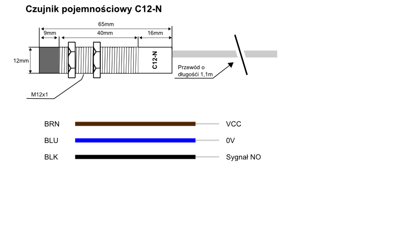
I am trying to set up a capacitive sensor not as a probe, but as a switch, which triggers some macro, whenever its "pressed". I am working with a Duet3 6XD, sensor information and config lines can be found below. My idea was to connect it as I have my endstops:
brown -> 24V
blue -> io_in_iso_neg
black -> io_in_iso_posHowever, this connection causes the sensor to not respond. Therefore, I did this:
brown -> 24V
blue -> io_GND
black -> io_inWith this connection, the sensor operates correctly, lighting up an LED whenever something is close to it, but the Duet3 does not recognize any change to the GPIO state:
21.11.2023, 16:05:50 	M409 K"sensors.gpIn[1]"
{
    "key": "sensors.gpIn[1]",
    "flags": "",
    "result": {
        "value": 0
    }
}
When I measure the voltage of the black wire, it is 8V or 9V depending on the state of the sensor. I figure, that changes between 0 and 3,3V would be needed, but do not know what to change to make it work.
; proximity sensor for pellet loading system M950 J2 C"io8.in" M581 P2 T2 -
I could not find the specs on that sensor as to what the output voltage should be in the "on/off" states.
Perhaps it needs a resistor from the output to ground - do you have a resistor you could try as a test? Perhaps something between 1K and 10K?
Frederick
-
@awitc try enabling the pullup resistor like so
M950 J2 C"^io8.in" -
The addition of "^" helped to bring the voltages to 0.7V and 3.3V respectively. I thought the pullup on the input is enabled by default. Thanks a lot!
I found also that testing the trigger with a M117 message makes the message show up only the first time the trigger is evoked. At least in my case.