Duet2 wifi + Duex5 with Nema34 Stepper Motor Driver
-
Hello, I'm new to this forum and I need some help with setting up an external drive for NEMA34 motor to Duet2 wifi + Duex5 configuration.
The idea is to add high flow pellet extruder to our 3d printer Modix big Meter. I'm not expert in this field so I need some advice.I know we need external drive to control big nema34 motor, so we have avaliable two of them: DM860H and MA860H. MA860H should be okay with an input signal of 3.3V, so maybe this one a is better choice.
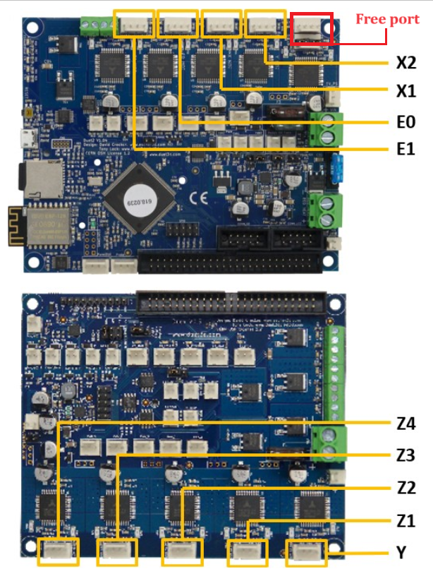
DueX5 board is already full with stepper motors for Z axis and Y axis, but we have one free port on Duet2 wifi board that could be used for maybe moving one stepper motor from DueX5 board and using DueX5 board as a connection for external motor driver.
If you have some good suggestion what would be the the best solution for this please share it with us. Pellet extruder is already developed by us and it only needs to be connected to a printer.
Our current config.g:
; Modix Big-Meter, Duex Expansion, Dual Printhead
; Configuration file for Duet WiFi (firmware version 3.3 or 3.4)
; Generated by Modix - Version 3.3 Config B; General preferences_________________________________________________________
G90 ; send absolute coordinates...
G90 ; ...but relative extruder moves=M83
M111 S0 ; Debug off
M555 P2 ; Set output to look like Marlin
M575 P1 B115200 S1 ; Set auxiliary serial port baud rate and require checksum (for PanelDue); Network_____________________________________________________________________
M550 P"Big Meter" ; set printer name
;M551 P"MODIX3D" ; Set password (optional)
M552 S1 ; enable network
;M552 P0.0.0.0 ; Uncomment this command for using Duet Ethernet board
M586 P0 S1 ; enable HTTP
M586 P1 S0 ; disable FTP
M586 P2 S0 ; disable Telnet; Drives_________________________________________________________________________
;Main board______________________________________________________________________
M569 P0 S0 ; Physical drive 0 . X1
M569 P1 S1 ; Physical drive 1 . X2
M569 P2 R-1 ; Physical drive 2 . Canceled
M569 P3 S1 ; Physical drive 3 . Main Extruder
M569 P4 S0 ; Physical drive 4 . Secondary Extruder
;Duex5 board_____________________________________________________________________
M569 P5 S0 ; Physical drive 5 . Y
M569 P6 S0 ; Physical drive 6 . Z1 (0,1000)
M569 P7 S0 ; Physical drive 7 . Z2 (0,0)
M569 P8 S0 ; Physical drive 8 . Z3 (1000,0)
M569 P9 S0 ; Physical drive 9 . Z4 (1000,1000);Settings_________________________________________________________
M584 X0:1 Y5 Z6:7:8:9 E3:4 P3 ; Driver mapping
M671 X-185:-185:1068:1068 Y1068:-46:-46:1068 S30 ; Anticlockwise
;___________________________________________________________________
M350 X16 Y16 E16:16 I1 ; Configure microstepping with interpolation
M350 Z16 I0 ; Configure microstepping without interpolation
M92 X100 Y100 Z2000 E453.051:418.5 ; Set steps per mm
M566 X240 Y360 Z30 E120:120 P1 ; Set maximum instantaneous speed changes (mm/min)
M203 X9000 Y9000 Z1000 E12000:12000 ; Set maximum speeds (mm/min)
M201 X2000 Y2000 Z120 E3000:3000 ; Set accelerations (mm/s^2)
M204 P1000 ; Set print and travel accelerations (mm/s^2)
M906 X1600 Y1600 E1500:1500 I50 ; Set motor currents (mA) and motor idle factor in per cent
M906 Z1800 I50 ; Set motor currents (mA) and motor idle factor in per cent
M84 S1000 ; Set idle timeout - 100 seconds; Axis Limits
M208 X0 Y0 Z-2 S1 ; set axis minima
M208 X0:1000 Y0:1000 Z-1:1000 ; set axis maxima; Endstops
M574 X1 S1 P"xstop + e0stop" ; configure switch-type (e.g. microswitch) endstop for low end on X via pin xstop
M574 Y2 S1 P"ystop" ; configure switch-type (e.g. microswitch) endstop for low end on Y via pin ystop; Z-Probe
M98 P"config_probe.g"
M557 X-13:985 Y22:1020 P15:15 ; define mesh grid
; The Z_offset value is now set in config_probe.g, not in config.g
; Adjust the values there, do not adjust anything here.; Heaters___________________________________________________________
M140 H-1 ; disable heated bed (overrides default heater mapping);E0_________________________________________________________________
M308 S0 P"e0temp" Y"thermistor" T100000 B4725 ; configure sensor 0 as thermistor on pin e0temp
M950 H0 C"e0heat" T0 ; create nozzle heater output on e0heat and map it to sensor 0
M307 H0 B0 S1 ; PID calibration
M143 H0 S350 ; set temperature limit for heater 0 to 285C;E1_________________________________________________________________
M308 S1 P"e1temp" Y"thermistor" T100000 B4725 ; configure sensor 1 as thermistor on pin e1temp
M950 H1 C"e1heat" T1 ; create nozzle heater output on e1heat and map it to sensor 1
M307 H1 B0 S1 ; PID calibration
M143 H1 S300 ; set temperature limit for heater 1 to 285C; Fans______________________________________________________________
M950 F0 C"fan0" Q500 ; create fan 0 on pin fan0 and set its frequency
M106 P0 S0 H-1 C"Primary blower fan" ; set fan 0 value. Thermostatic control is turned on
M950 F1 C"fan1" Q500 ; create fan 1 on pin fan1 and set its frequency
M106 P1 S0 H-1 C"Secondary blower fan" ; set fan 1 value. Thermostatic control is turned on
M950 F2 C"duex.fan7" Q500 ; create LED on pin fan2 and set its frequency
M106 P2 S0 H-1 C"LED" ; Disable fan channel for LED
M106 P2 S255 ; LED on by default
M950 F3 C"duex.fan5" Q500 ; create fan 3 on pin fan1 and set its frequency
M106 P3 S255 H0 T45 ; set fan 3 value. Thermostatic control is turned on
M950 F4 C"duex.fan6" Q500 ; create fan 4 on pin fan1 and set its frequency
M106 P4 S255 H1 T45 ; set fan 4 value. Thermostatic control is turned on; Tools______________________________________________________________
;T0_________________________________________________________________
M563 P0 S"E0 Primary" D0 H0 F0 ; define tool 0
G10 P0 X0 Y0 Z0 ; set tool 0 axis offsets
G10 P0 R0 S210 ; set initial tool 0 active and standby temperatures to 0C;T1_________________________________________________________________
M563 P1 S"E1 Secondary" D1 H1 F1 ; define tool 1
G10 P1 X0 Y49 Z0 ; set tool 1 axis offsets
G10 P1 R0 S210 ; set initial tool 1 active and standby temperatures to 0C; Custom settings__________________________________________________
M950 J0 C"duex.e2stop"
M581 T1 P0 S0 R1
M591 D0 P7 C"e1stop" S1 L4.2 E10 R10:1000 ; Regular filament sensor for E0M591 D1 P1 C"duex.e3stop" S1 ; Regular filament sensor for E1
; Automatic power saving____________________________________________
M911 S22.5 R29.0 P"M913 X0 Y0 G91 M83 G1 Z3 E-5 F1000" ; Set voltage thresholds and actions to run on power loss. Power Failure Pause
Thanks!
Matic -
@ma3d
You can't use the stepper motor output on either board to drive an external stepper motor driver, as it outputs voltage/current for each motor phase, not step and direction pulses. Your choices are:- Use a free motor driver (7, 8 or 9) output on the Duex. See https://docs.duet3d.com/Duet3D_hardware/Duet_2_family/DueX2_and_DueX5#using-a-duex5-with-external-drivers
Usually you have to disable all three internal drivers, but there is a workaround:
If you only want to control one or two external steppers, and keep four or three internal drivers working, don't switch the board to DueX2 mode. Then, disable the internal driver by removing the jumper (v0.11) or cutting the trace (v0.10). You will get driver errors when you disable the internal driver, but you can silence these by adding
M569 P[driver number] R-1to config.g. You will not be able to use the Enable signal on the external driver, but step and direction pins will still control it.- Connect the external driver to the CONN_LCD header. If you have a PanelDue connected to this via ribbon cable, you will have to move it to using just the 4-wire cable connected to the 'PanelDue' connector. You will lose the ability to use the PanelDue SD card.
For the rest of the options and configurations, see https://docs.duet3d.com/en/User_manual/Connecting_hardware/Motors_connecting_external
Ian
TronXY X5S with Duet 3 MB6HC and Roto toolboard : Cartesian bed-slinger with Duet 3 Mini 5+ WiFi and 1LC : RRP Fisher Delta v1 with Duet 2 Maestro : Polargraph with Duet 2 WiFi
- Use a free motor driver (7, 8 or 9) output on the Duex. See https://docs.duet3d.com/Duet3D_hardware/Duet_2_family/DueX2_and_DueX5#using-a-duex5-with-external-drivers
-
@droftarts Hello,
thank you for fast response. I have read about the option of disabling the motor drivers, but I wasn't 100% sure about it. Okay, i think that I will chose option for disabling only one driver on duex5 board as I need the lcd.So for doing this I will have to:
-move one stepper motor from duex board to duet2wifi board free stepper motor output + sort this out in config.g
-remove jumper or cut connection on one output (7,8 or 9) on duex5 board
-add M569 P[driver number] R-1 to config.g.
-solder cable/pin to step, dir, en of chosen output and connect them to step, dir, en of my external driver.
-add a comand in config.g to use this output for extruderWill I get +step, + dr + en from those pins on duex? Do I have to use common ground for -step, -dir - en? Or is it just the opposite? Also is there a way of getting 5V signal to my external driver?
Thanks for your help!
Matic -
@ma3d said in Duet2 wifi + Duex5 with Nema34 Stepper Motor Driver:
-solder cable/pin to step, dir, en of chosen output and connect them to step, dir, en of my external driver.
This depends on the version of the Duex you have. If you have v0.11 (which has been the current version for at least a year), there are 5 pin headers for the external drivers to connect to. On the v0.10 and earlier, yes, you need to solder something to the vias. I'd tend to use a Molex pin header.
Will I get +step, + dr + en from those pins on duex? Do I have to use common ground for -step, -dir - en? Or is it just the opposite? Also is there a way of getting 5V signal to my external driver?
Yes, I think you get +step, + dr + en from the pins, with a common ground. Though if you are going to leave the board in Duex5 mode, you can't use the enable pin, so the stepper driver will just have to be enabled from power up. The signal is 3.3V, so if your external driver needs 5V, you need to level shift the signal to 5V. A non-inverting 74HCT series gate or buffer such as 74HCT08 can be used to do this. Much easier to choose a driver that accepts 3.3V input!
Ian