Tool Change Verification Macro
-
I’d just like to share this for anyone that might be interested.
I have a tool changer that I built based on the E3D tool changer. There are currently three tool heads on it all with the ToolBoard 1LC. Occasionally, a tool change will fail and I needed a way to check for that and pause the print.
I purchased and installed the TRCT1010 optical sensors as recommended by the documentation. Next, I printed a flag to trip the sensor and with the “Object Model” plug in I was able to command a tool change and verify that everything was working as intended. (0 = tool is docked, 1 = not docked). Finally, a macro will loop over all tools and check that the selected tool is not docked and that all others are. I call this macro first thing in the tpost.g for each tool.
Hope this helps someone!
var iter = 0; var numTools = 3 var checkValue = 0; 0 = docked if state.currentTool = -1 ; if there's no tool selected, return M99 while var.iter<var.numTools ; set check value to 1 if i = current tool if var.iter = state.currentTool set var.checkValue = 1 else set var.checkValue = 0 if sensors.gpIn[var.iter].value != var.checkValue ; tool change failed M291 P"tool change failed" S2 M98 P"pause.g" set var.iter = var.iter+1 M99 -
@Alex-0 could you post a link to the documentation you are referring to? Thanks!
-
@jens55 Sure thing. The section I used is under "connecting peripherals" and "adding an IO_3 Switch"
https://docs.duet3d.com/Duet3D_hardware/Duet_3_family/Duet_3_Toolboard_1LC
-
@Alex-0 Thank you very much for sharing.
-
@Alex-0, sorry for being a bit dense but do you think you might be able to post a picture showing the physical arrangement that you are using for the flag and switch and how they interact?
Setting up a tool change verification is on my list of things to do and your post has brought that back to the top of the list. -
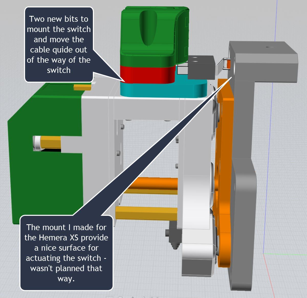
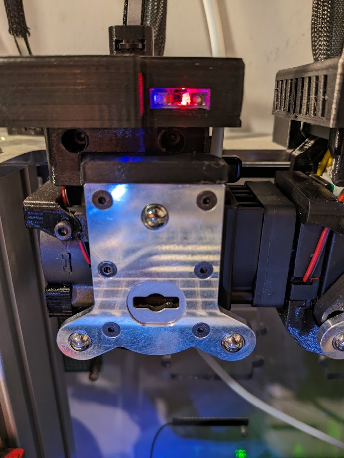
@jens55 The other option to having a switch/sensor on each tool is to add a switch to the e3d toolhead and use that to confirm that the tool has been picked up correctly. That's what I did. On my toolchanger there was already an extra wire that ran to the toolhead so I just used that. The advantage of this is that it gives you a direct readout of having a tool attached rather than you having to work out that you have a tool attached by checking to see if a tool is not docked... I suppose you could do both, but I never had an issue with tools not staying on the dock. A downside is that I had to modify the support structure for each tool to give the toolhead switch something to push against, but you might be able to avoid that if you use a different switch (I used the same type of switch as used for the existing z-probe/z-endstop) or mounting point.
If you are interested let me know and I'll post a few pictures of my setup.
-
@gloomyandy said in Tool Change Verification Macro:
If you are interested let me know and I'll post a few pictures of my setup.
Yes please!
-
-
@jens55 Here you go....
Switch mounted on the toolhead...
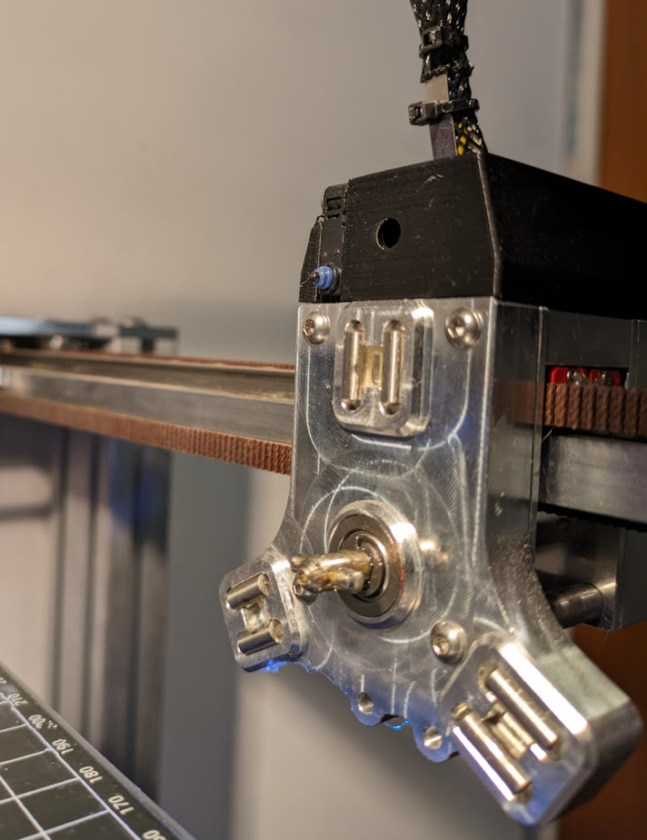
Modified tool support structure to provide something for the switch to push on...
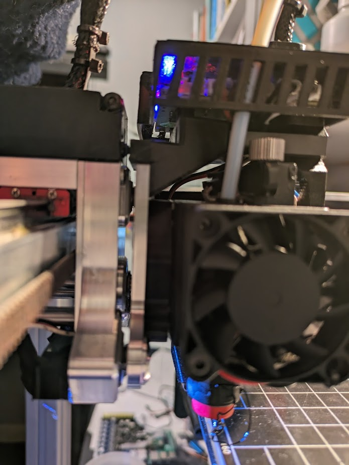
You can just about see how the switch contacts the modified support in this picture (sorry it is out of focus)...
-
@fcwilt @gloomyandy Your solution with the micro switch on the tool head is much more elegant than mine. Had I thought of this while designing, I would have implemented something similar. I wanted something quick and didn't feel like running wires back up to the tool head or re-designing both the tool head and the tools, so I went with this approach. Plus, this let me dig a little deeper into the Duet. I had no idea about the object model and how powerful it is.
@jens55 First image is of the TCRT1010 sensor soldered on. Next is a top down image of the tool and dock. I got lucky with the sensor being located at the very front of the tool which made the flag implementation relatively straight forward. After playing around a bit, I found I got the most consistent results with card stock glued on. Last is of the front of the dock. The flag's position can be set via the channel in the extrusion.
Total cost was <$10 + shipping from DigiKey and a few evenings of tinkering. Some drawbacks to this approach are that soldering small pins is required and that you can't completely enclose the tool board.
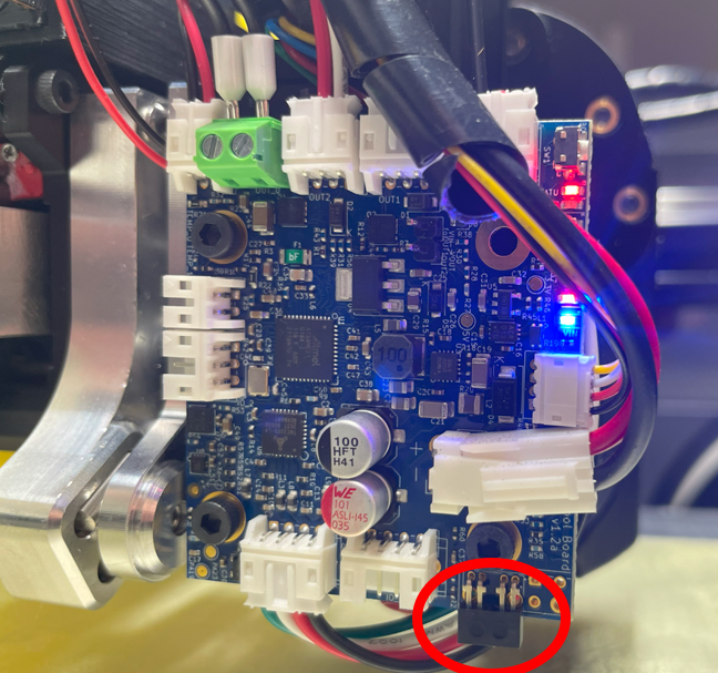
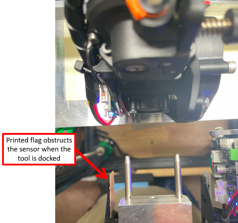
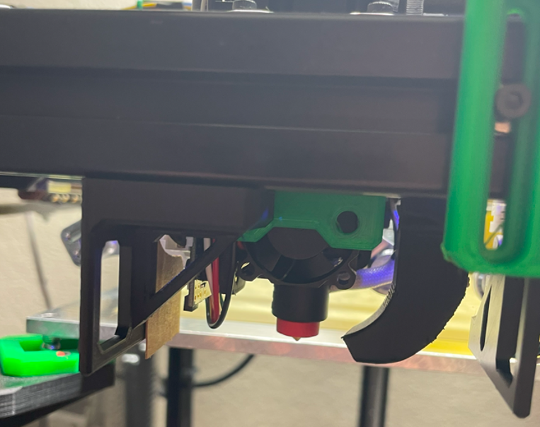
-
@Alex-0 Nice solution. With how I have my toolboard mounted using a switch mounted on the board wasn't really an option for me. My toolhead has wiring running to it for the "attached" and z probe switches as well as for Neopixels (that both provide a status display and also provide lighting on the nozzle to make it a little easier to see what is going on), so I was already running extra wires to it. Though having said that I think in the standard e3d wiring harness that I had there was an extra wire or two (was a long time ago I did this so can't really remember).
I look after the stm32 port of RRF and so to a big extent my toolchanger is used for firmware testing. As a result I currently have 4 tools all using Hemeras (two of them using the original motor, 2 using the XS motor). One is connected directly to the control board (a Fly super 8), one is connected using a Fly RRF36 toolboard and the other two use Duet 1LC boards (though I'm probably going to be replacing one of those shortly, as I have a hew toolboard to test).
-
Thanks guys, this gives me all kinds of ideas.
