+3°C in the temperature lecture after upgrade to PT1000
-
Hello!!
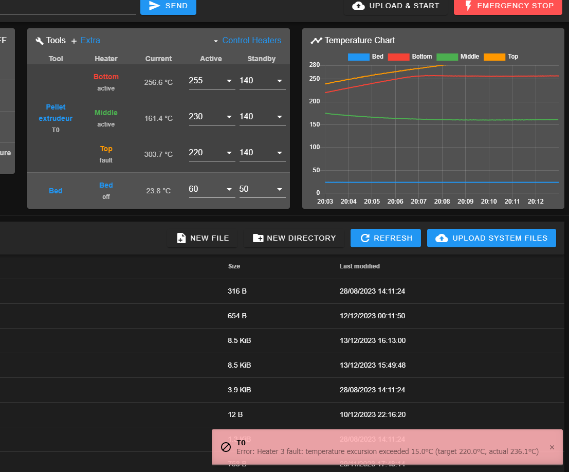
I've been upgrading a 3D printer and decided to change my thermocouples to PT1000 sensors. The printer has 3 heaters, thus 3 temperature sensors. When I changed and installed the PT1000 sensors, 2 of them are working well, but the one in the middle shows a 3-degree difference from the desired temperature (fig.1) and can't seem to regulate itself. I tried adjusting the R parameter, thinking it might be the issue, but it worsened the reading instead. Also, changing the parameters of the sensor I want to fix affects the other two sensors.
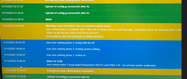
I also attempted to perform the PID tune again in case it would help, but I received a warning: "heater behavior was not consistent during tuning" for H2 and H3 (fig.2).
Could you provide me with an idea of what might be happening?
Fig.1
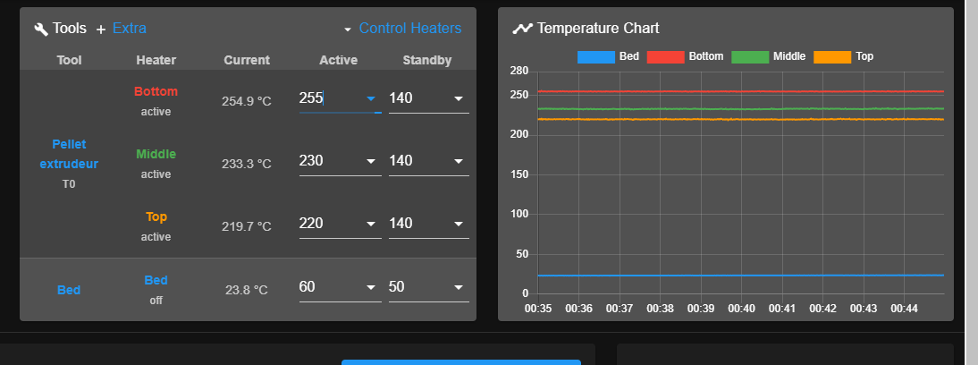
Fig.2
I'm using RepRapFirmware for Duet 3 MB6HC version 3.3 (2021-06-15 21:45:47) running on Duet 3 MB6HC v1.01 or later (standalone mode)
And Config.g
Thank you very much.; General preferences
M575 P1 S1 B57600 ; enable support for PanelDue
G90 ; send absolute coordinates...
M83 ; ...but relative extruder moves
M550 P"Gigabot X UWO edition" ; set printer name; Network
M552 P192.168.100.8 S1 ; enable network and set IP address
M553 P255.255.255.0 ; set netmask
M554 P192.168.100.254 ; set gateway
M586 P0 S1 ; enable HTTP
M586 P1 S1 ; enable FTP
M586 P2 S0 ; disable Telnet; Drives
M569 P0.0 S2 ; physical drive 0.0 goes forwards X
M569 P0.1 S1 ; physical drive 0.1 goes forwards YR
M569 P0.2 S0 ; physical drive 0.2 goes Backwards YL
M569 P0.3 S0 ; physical drive 0.3 goes forwards ZR n ZL
M569 P0.4 S1 ; physical drive 0.4 goes forwards Crammer
M569 P0.5 S0 ; physical drive 0.5 goes forwards Extruder
M584 X0.0 Y0.1:0.2 Z0.3 E0.4:0.5 ; set drive mapping
M350 X16 Y16:16 Z16 E16:16 I1 ; configure microstepping with interpolation
M92 X53.335 Y59.26:59.26 Z2015.75 E35.00:520.00 ; set steps per mm E crammer : extruder
;M201 X5000.00 Y3000.00:3000.00 Z100.00 E9000.00 ; Save set accelerations (mm/s^2)
M201 X500.00 Y500.00 Z20.00 E900.00 ; TEST set accelerations (mm/s^2)
;M203 X10740.00 Y6810.00:6810.00 Z480.00 E3600.00 ; SAVE set maximum speeds (mm/min)
M203 X10740.00 Y6810.00 Z480.00 E3600.00 ; TEST set maximum speeds (mm/min)
;M566 X5000.00 Y2000.00:2000.00 Z60.00 E500.00 P1 ;SAVE set maximum instantaneous speed changes (mm/min)
M566 X900.00 Y900.00 Z60.00 E500.00 ; TEST set maximum instantaneous speed changes (mm/min)
M204 P5100 T20000 ; set printing and travel accelerations (mm/s^2)
M906 X2800 Y2000:2000 Z2000 E850:2750 I30 ; set motor currents (mA) and motor idle factor in per cent
M572 D1 S0.03 ;Pressure advance
M84 S30 ; Set idle timeout; Axis Limits
M208 X0 Y0 Z0 S1 ; set axis minima
M208 X570 Y754.5 Z800 S0 ; set axis maxima; Endstops
M574 X1 S1 P"!io1.in" ; configure switch-type (e.g. microswitch) endstop for low end on X via pin io1.in
M574 Y2 S1 P"!io2.in+!io3.in " ; configure switch-type (e.g. microswitch) endstop for High end on YR and YL via pin io2.in + io3.in
M574 Z1 S1 P"!io4.in+!io5.in" ; configure switch-type (e.g. microswitch) endstop for low end on ZR and ZL via pin io4.in
;M574 A1 S3 ; configure switch-type (sensorless) endstop on Crammer
;M915 A S3 R0 F0 ; configure switch-type (sensorless) endstop on Crammer
;Z-probe
;M950 S0 C"io7.out"
;M558 P9 C"io7.in" H3 R0.5 F220 T6000 A1 B1 ; disable Z probe but set dive height, probe speed and travel speed
G31 P100 X20 Y-10 Z1.6
M557 X50:570 Y50:754.5 S80 ; define mesh grid; Heaters
M308 S0 P"spi.cs0" Y"thermocouple-max31856" A"Bed" T "k" F 60 ; configure sensor 0 as thermocouple via CS pin spi.cs0
M950 H0 C"out0" T0 ; create bed heater output on out0 and map it to sensor 0
M307 H0 B0 R0.186 C697.8 D3.40 S1.00 V23.9 ; disable bang-bang mode for the bed heater and set PWM limit
M140 H0 ; map heated bed to heater 0
M140 S60 R50 ; heated bed "S" active temp "R" standby temp
M140 S-273.1 ; switch off bed heater
M143 H0 S110 ; Heated Bed Max temp
M308 S1 P"temp1" Y"pt1000" A"Bottom" ; configure sensor 1 as PT1000 on pin temp1
M950 H1 C"out1" T1 ; create heater 1 and map sensor 1
M307 H1 B0 R0.255 C1098.9 D15.33 S1.00 V24.1 ; disable bang-bang mode for heater and set PWM limit
;M308 S1 P"spi.cs1" Y"thermocouple-max31856" A"Bottom" ;T "k" F 60 ; configure sensor 1 as thermocouple via CS pin spi.cs1
;M950 H1 C"out1" T1 ; create nozzle heater output on out0 and map it to sensor 1
;M307 H1 R0.227 C1317.237:1317.237 D12.76 S1.00 V23.1 B0 I0 ; disable bang-bang mode for heater and set PWM limit
M143 H1 S280 ; set temperature limit for heater 1 to 300C
M308 S2 P"temp2" Y"pt1000" A"Middle" ; configure sensor 1 as PT1000 on pin temp1
M950 H2 C"out2" T2 ; create heater 1 and map sensor 1
M307 H2 B0 R0.326 C953.9 D12.95 S1.00 V24.1 ; disable bang-bang mode for heater and set PWM limit
;M308 S2 P"spi.cs2" Y"thermocouple-max31856" A"Middle" ;T "k" F 60; configure sensor 2 as thermocouple via CS pin spi.cs2
;M950 H2 C"out2" T2 ; create nozzle heater output on out1 and map it to sensor 2
;M307 H2 R0.387 C763.827:763.827 D8.04 S1.00 V23.1 B0 I0 ; disable bang-bang mode for heater and set PWM limit
M143 H2 S280 ; set temperature limit for heater 1 to 280C
M308 S3 P"temp3" Y"pt1000" A"Top" ; configure sensor 1 as PT1000 on pin temp1
M950 H3 C"out3" T3 ; create heater 1 and map sensor 1
M307 H3 B0 R0.302 C728.2 D15.75 S1.00 V24.1 ; disable bang-bang mode for heater and set PWM limit
;M308 S3 P"spi.cs3" Y"thermocouple-max31856" A"Top" ;T "k" F 60 ; configure sensor 3 as thermocouple via CS pin spi.cs3
;M950 H3 C"out3" T3 ; create nozzle heater output on out2 and map it to sensor 3
;M307 H3 R0.329 C608.587:608.587 D10.43 S1.00 V23.1 B0 I0 ; disable bang-bang mode for heater and set PWM limit
M143 H3 S280 ; set temperature limit for heater 3 to 280C; Fans
M950 F0 C"out9" Q5 ; create fan 0 on pin out8 and set its frequency
M106 P2 S255 H-1 ; set fan 0 value. Thermostatic control is turned off
M950 F1 C"out8" Q500 ; create fan 1 on pin out9 and set its frequency
M106 P1 S255 H-1 ; set fan 1 value. Thermostatic control is turned off; Tools
M563 P0 S"Pellet extrudeur" D0:1 H1:2:3 F0 ; define tool 0
M567 P0 E1:1 ; define Mix ratio
M568 P0 S1 ; Activation
G10 P0 X0 Y0 Z0 ; set tool 0 axis offsets
G10 P0 R140,0:140,0:140 S140,0:140,0:140 ; set initial tool 0 active and standby temperatures to 0C; Miscellaneous
M501 ; load saved parameters from non-volatile memory
;Automatic power saving
M911 S20 R22 P"M913 X0 Y0 G91 M83 G1 Z3 E-5 F1000" ; set voltage thresholds and actions to run on power loss
Thank you very much.
-
@Casugo First, check all PT1000 sensors read the same, by checking their resistance at room temperature. Refer to the PT1000 data sheet to check the resistance is correct: https://www.sterlingsensors.co.uk/pt1000-resistance-table
Then see the section here on calibrating the ADC inputs: https://docs.duet3d.com/en/User_manual/Connecting_hardware/Temperature_connecting_thermistors_PT1000#temperature-calibration-and-adc-tuning
Duet 3 Mainboard 6HC and 6XD have two banks of ADC inputs, and sometimes exhibit different errors on different ADC banks. The on-board hardware can only apply the same compensation to both banks. As a result, the hardware self-calibration isn't perfect.
Calibration can be automatic, semi automatic or manual. Try each method in turn until you get satisfactory temperature readings.
Ian
Bed-slinger - Mini5+ WiFi/1LC | RRP Fisher v1 - D2 WiFi | Polargraph - D2 WiFi | TronXY X5S - 6HC/Roto | CNC router - 6HC | Tractus3D T1250 - D2 Eth
-
Thank you for your response.
Update:
- Yes, at room temperature all sensors read the same temperature.
- I measured the resistance in all the PT1000s and all of them indicate 1083 ohm which quite goe according to the datasheet (at 22°C --> 1085.7 ohm)
- I performed the semi-automatic calibration (fig.1) and retry heating and I encounter the same issue +3°C in the "middle" indication.
- I performed the manual calibration first with the 100K resistor (fig.2) and the indication was 25.5°C (fig.3). Then with the 220 (fig.4) and the indication was 236.7°C (fig.5). This indications showed that the system is well calibrated. However, when I heat again I still having this +3°C.
- I changed the sensor for a new one (measured the resistance and gave 1083ohm like the others)
then heating and now the indication is +7 °C (fig.6)
Fig.1
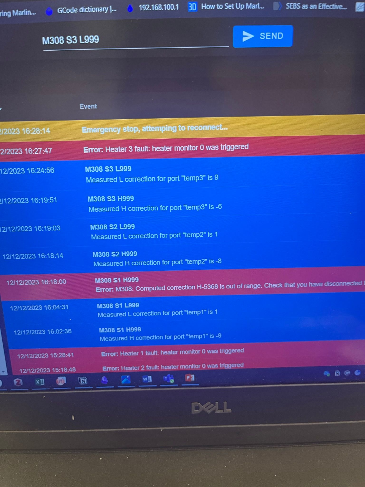
Fig.2
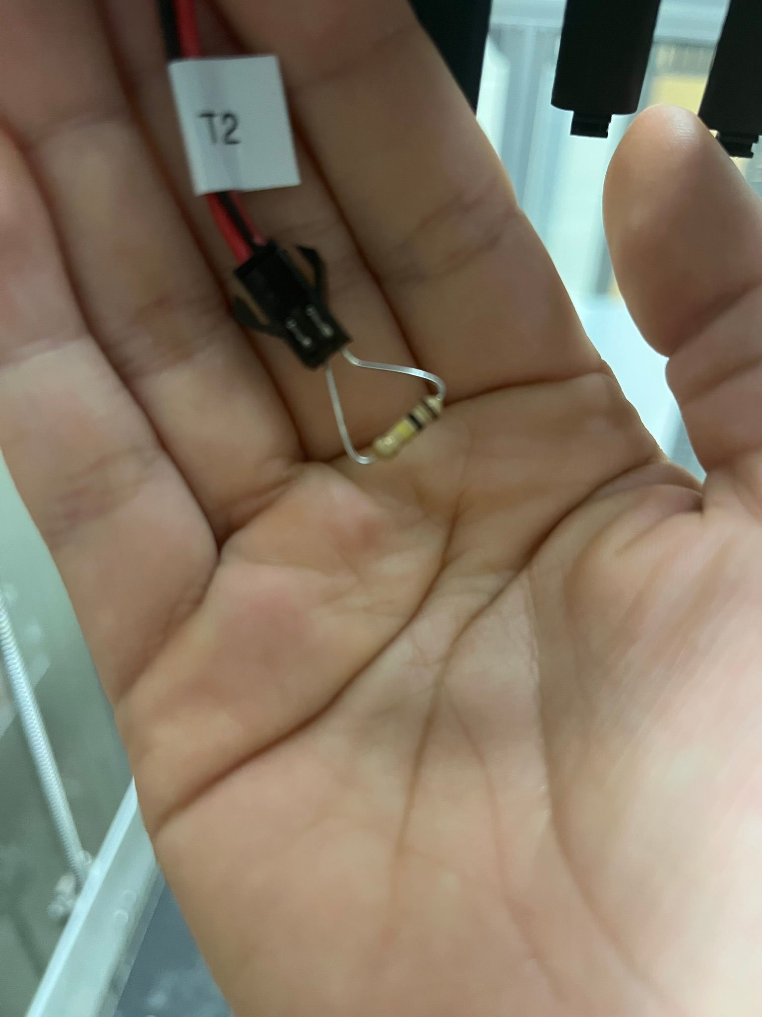
Fig.3
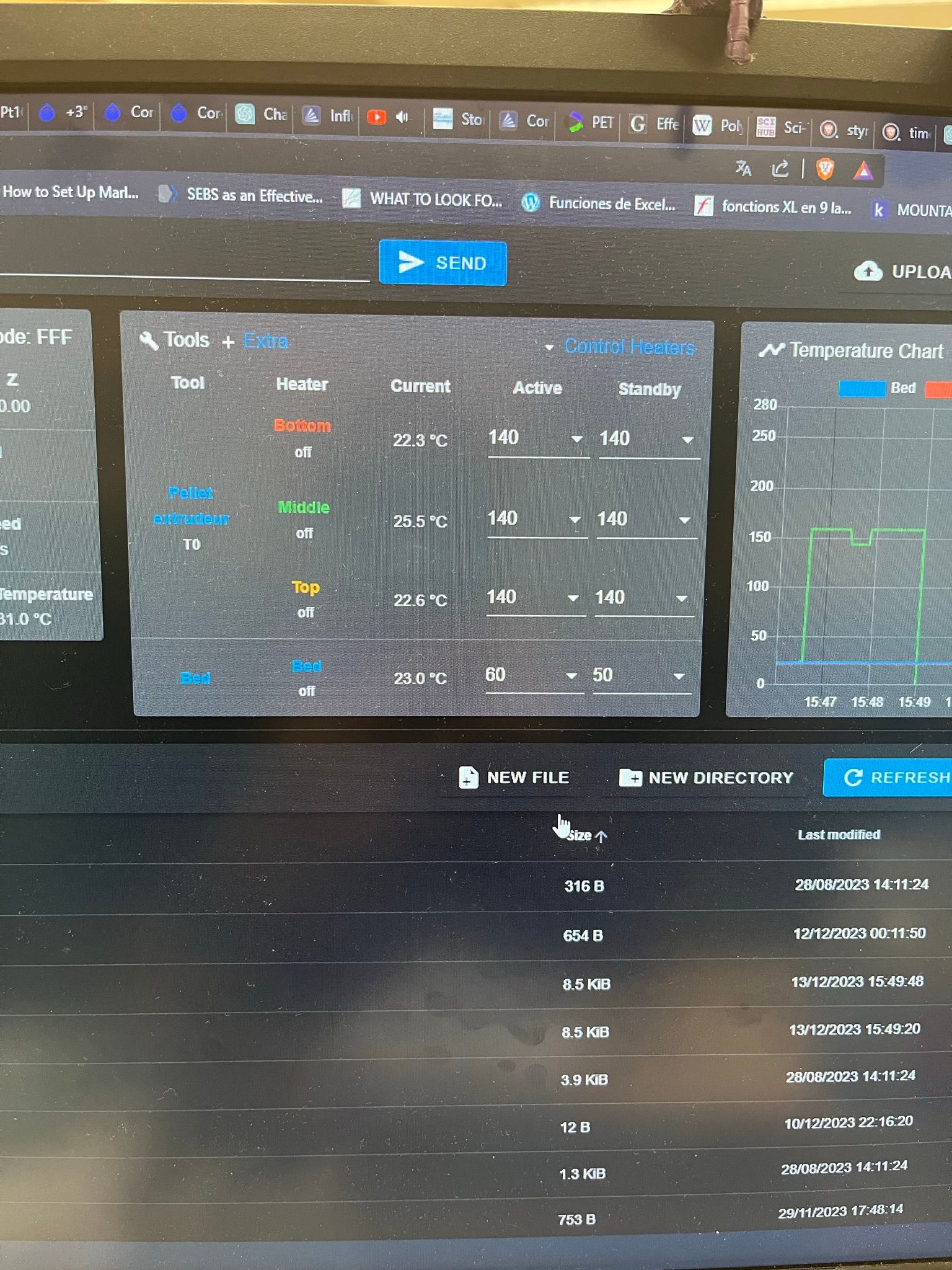
Fig.4
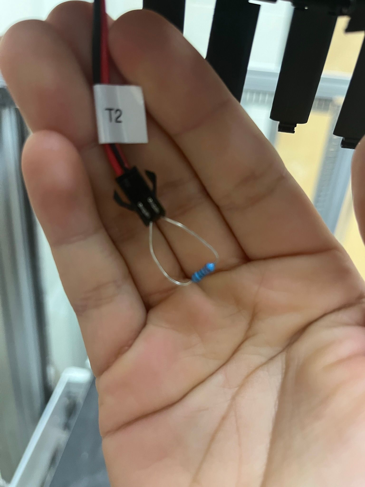
Fig.5
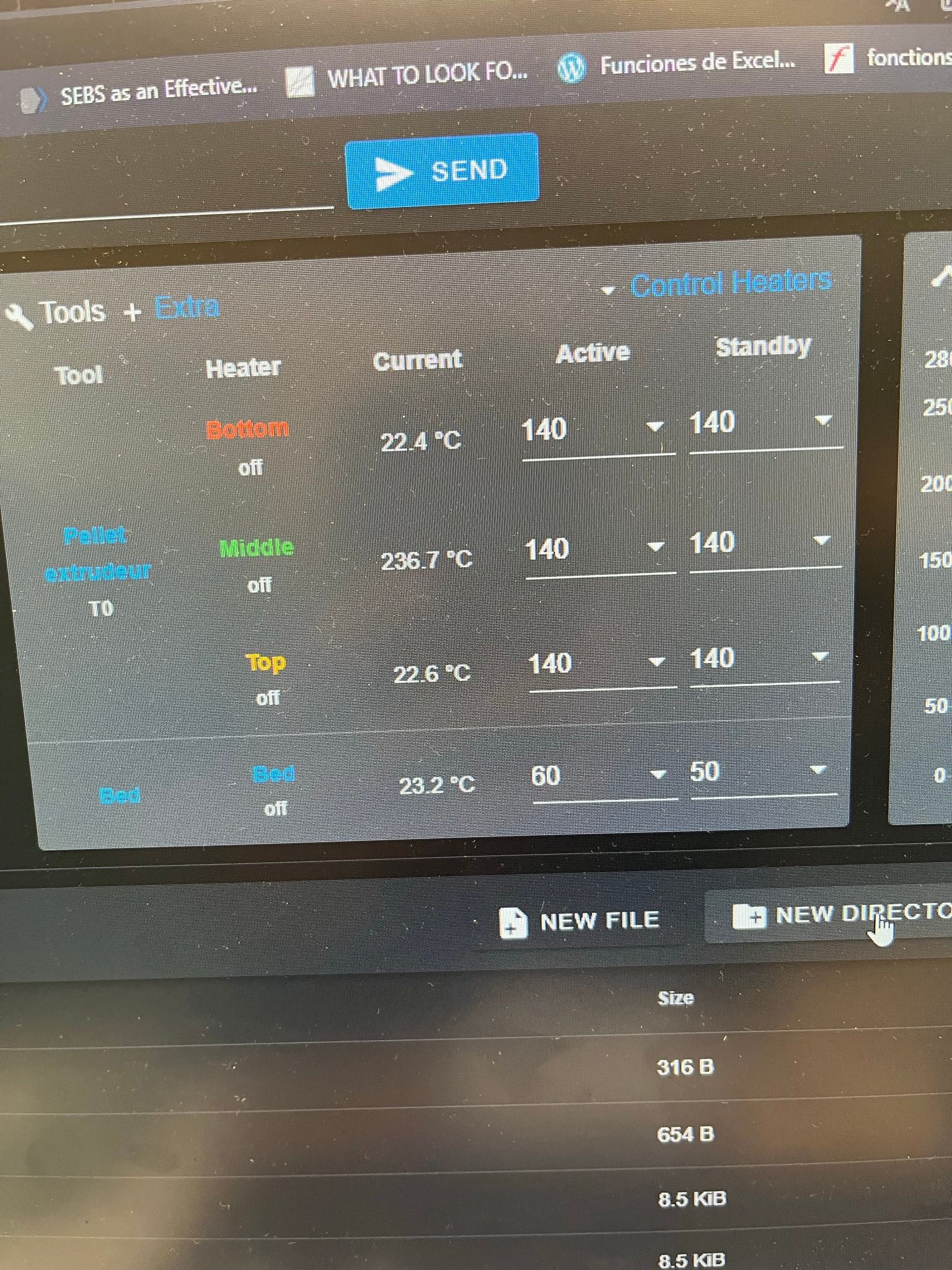
Fig.6
-
@Casugo are the 3 heaters heating different parts of the same hot end? If so then the explanation for the lack of control could be that you are getting heat creep from the top and bottom sections to the middle section. It's difficult to PID-control multiple heaters that have close thermal coupling.
In your Fig. 3 the sensors all appear to read close to room temperature, although the middle sensor is reading about 3C higher. If this is the case after the machine has been left turned off for a long time, so that all temperatures should be the same, then I think the most likely explanations are that either that PT1000 has a different behaviour from the others, or there is some additional resistance in the connection to it.
What happens if you swap the connections to the middle PT1000 and one of the others at the Duet, and adjust your
M307M308 commands accordingly? Does the issue remain with that PT1000, or remain with the port on the Duet?Duet WiFi hardware designer and firmware engineer
Please do not ask me for Duet support via PM or email, use the forum
http://www.escher3d.com, https://miscsolutions.wordpress.com -
Hello!
-
Yes, 3 heaters are heating different parts of the same hot end as it is a large-scale pellet machine so they heat the screw in three different parts.
-
Yes; I know we can get this heat creep however before the machine was connected to K-type thermocouples, I did not have this problem .
-
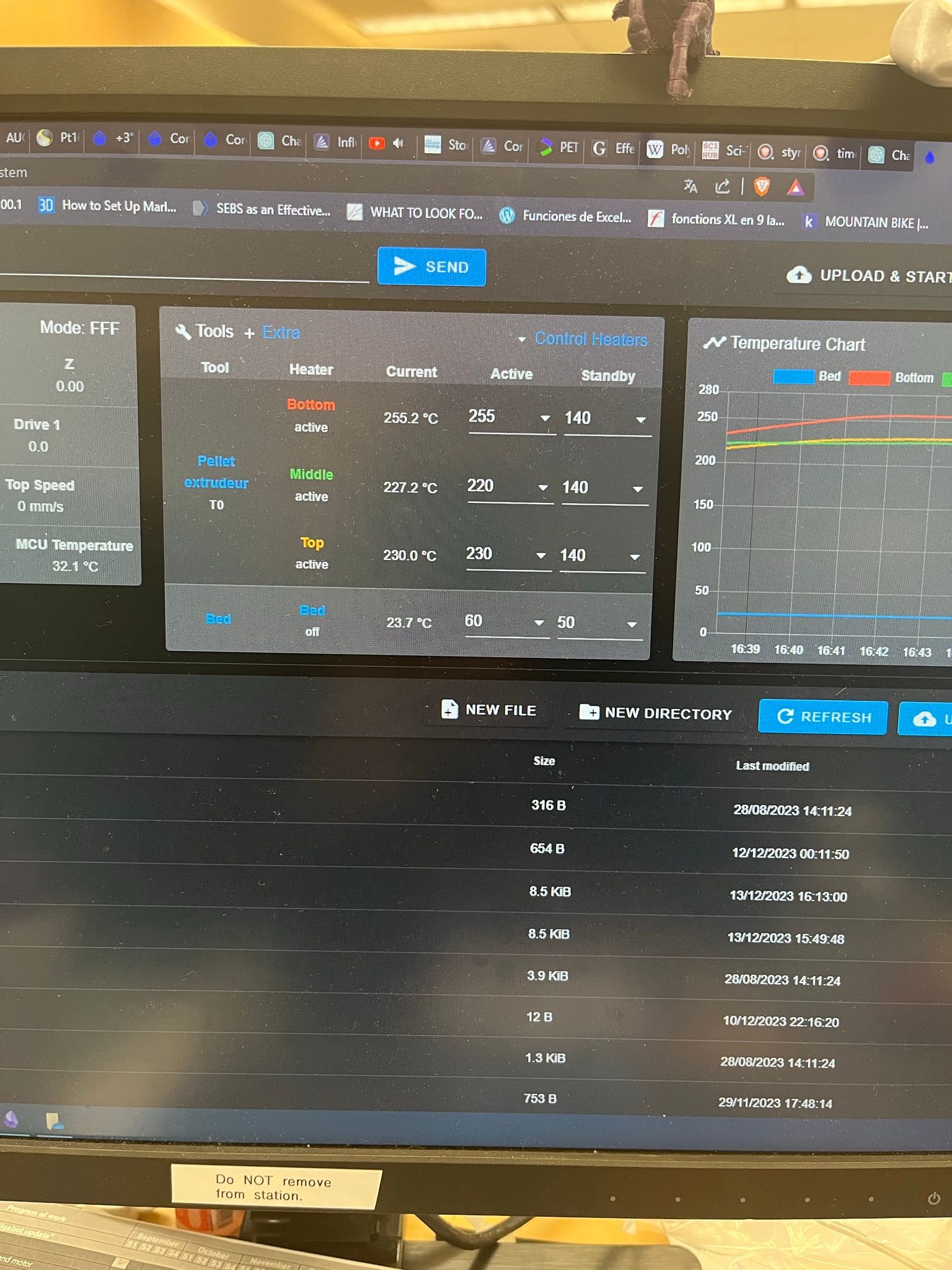
Fig 3. is a picture that I took when doing the manual calibration so there was the 100K resistor at the input therefore it will show 25°C .However, normally arrangementnot calibration and at ambiance temperaure, all three sensors show the same 22°C . The problem came when I heat above 200°C the middle gets this +3 now +80°C

-
I have changed the PT1000 to a new one and that is when I get the +7°C. I have come back to the previous and now it shows +8°C
-
I swaped "middle" with "top" now I get this:
-
-
@Casugo if you set all 3 heaters to the same temperature, does it maintain a stable temperature with all 3 sensors reading the same value?