Multiple Motion System
-
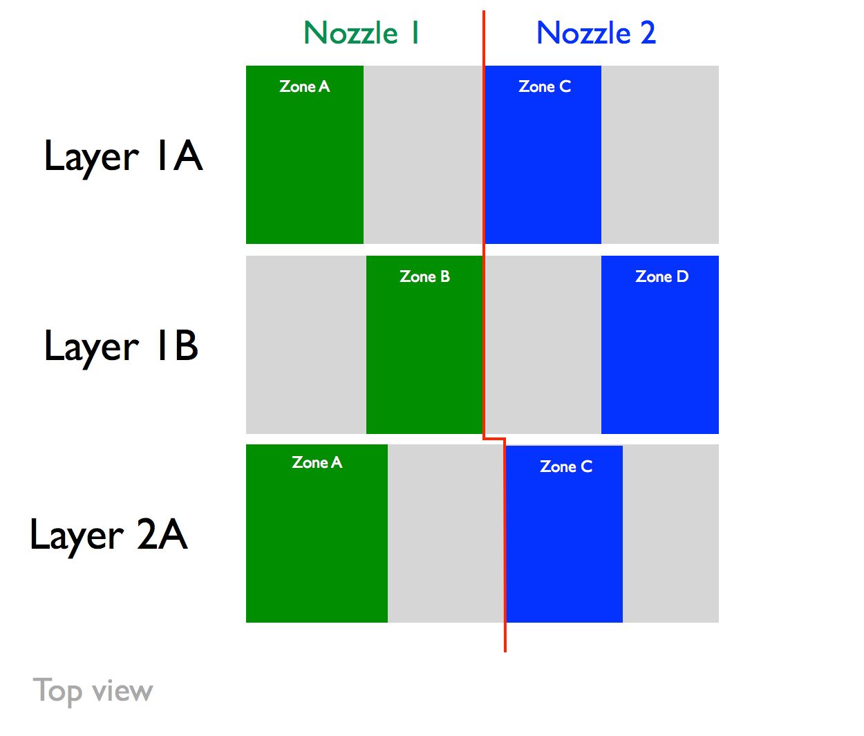
@o_lampe No, the zones are in a row, not a square. See image. This is the top view of the zones (perpendicular to Z axis). Nozzle 1 would always left of the red line in Zone A or B, and Nozzle 2 would always be to the right of the red line. So the sequence is:
- Layer 1A prints: Nozzle 1 stays in Zone A, Nozzle 2 stays in Zone C.
- Layer 1B prints: Nozzle 1 stays in Zone B, Nozzle 2 stays in Zone D.
- Layer 2A prints: In Layer 2A, the zones shift slightly so that there is an interweaving joint between layers instead of a butt joint (hence shift of the red line).
- Layer 2B prints.
- Layer 3A prints: In Layer 3A, the zones shift slighty back to the same positions in Layer 1, and the process loops.
Nozzle 1 would move to the left when not printing while Nozzle 2 would move to the right. As long as the toolhead is narrower than the adjacent zone, and each "half" layer is finished before printing the other "half" layer, collision is not possible.
How difficult would it be to script something like this? It seems it would be much simpler than true collision avoidance collaboration, particularly if the single part was divided into 4 parts (one for each zone) with the interweaving layers in CAD.
-
@loddie I think openScad is a good way to split an .stl object in four sections, even with interweaving in z-direction.
The slicer has to create two files, one for each nozzle. There are already ways to tell a slicer it is a dual-"color" object (eg. zone a + zone b)
You have to create two tools for each nozzle (although they are technically identical)
This way you make sure, the zones print in the right order.The only difficulty is to synchronize both gcode-streams when:
- changing zones or start the next layer
- wait for the other stream to finish.
The second option is easier to implement by adding some conditional tool-change gcode, but it can cause oozing.
-
@o_lampe said in Multiple Motion System:
openScad
Thanks! I'm not familiar with openScad but am quite proficient with Fusion360. It seems slicing the model is the easy part. As you mention, it the synchronization that I am not sure about.
-
@loddie The good thing about openScad is, that you can use parameters. You only have to write the script once and can later adapt it to a new object.
(things like first layer height, # of perimeters, layer height and layer width )
Just out of curiosity I'll try to write a script, although I don't have a printer to test it. -
Re: synchronizing two gcode streams
@chrishamm
Would it be possible to simulate two gcode files and filter out their layer-times?
It would then be possible to postprocess the files and change printspeed multiplier (M220) for each layer to make them match. -
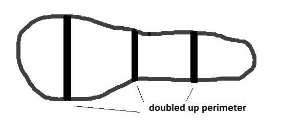
@loddie Are you aware that splitting the object will cause twice as many perimeters at places you'd probably won't like to see any...
At every zone-border and between the two nozzles
Quick hand drawing
-
@o_lampe Good idea! Some have mentioned that different speeds results in difference in print quality if not appearance. Perhaps this could be addressed by having the outer wall speeds, the same, but have differing infill speeds.
-
@o_lampe I had not thought of that. Thank-you for pointing it out.
This application would be TPU, which I have yet to print with (mainly ABS/PLA). Does TPU require a perimeter for an object the size on an infill? If so, seems the G-Code would need to be edited. Or, perhaps the perimeter could be designed into the CAD file so that it exists for adhesion, but eliminate the perimeter from the slicer settings.
-
@loddie TPU sticks pretty good to the bed, so It would be possible to print without perimeter.
But then the interweaving part would probably look messy, because infill-slicing is a different beast.
Do you want to print the first layer(s) solid or start with the infill right away?There is another option to match zone/layer-times.
If you split the object by equalizing the surface areas, they would automatically have the same print duration.
The design would have to be uniform along the z-axis for that.
I'm not sure if a surface-calculation tool exists amongst slicers. -
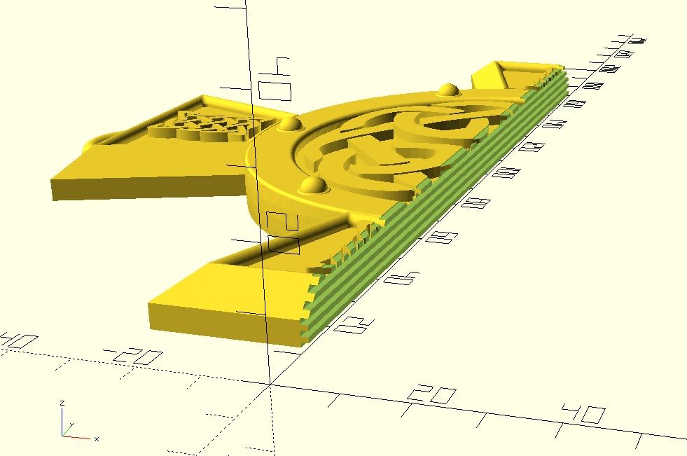
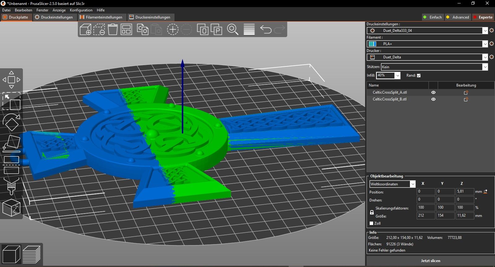
Just a little heads-up about the STL-splitting.
It's a bit tedious, but doable with OpenScad. Maybe fusion360 or other CAD programs have better options, but it's a starting point.
I've chosen a coarse interweaving pattern, which is 3 layers high.
Here are screenshots of a split object and how it looks in PrusaSlicer.