Multiple Motion System
-
Re: Beta testers for multiple motion system support
Given RRF 3.5 adds multiple motion system support and Duet has provided support for it, I was quite excited to design and build a new 3D printer specially for independent dual extruder simultaneous/"collaboration" printing of single objects with the objective of minimizing print times in a potentially commercial application. However, with David's (DC42) description of the collaboration function, my enthusiasm was tempered a bit:
"It's up to the slicer to do proactive avoidance. The collision detection is there as a backup."
This leads to several questions:
- Has anyone successfully used this collaboration mode yet?
- What slicers have the cabability to create collaboration modes to be used with RRF/Duet (or any firmware/controller)?
- How much effort is it to set this up in the compatible slicers? E.g., does the slicer do all the work or does the user have tinker/manually edit g-code? How much actual/processing time (minutes) is needed to calculate the toolpaths?
I plan to build a dedicated dual extruder 3D printer specifically for this function preferably with Duet components, so any input is appreciated. Outside the Autodesk Escher, which seems to not have successfully taken off commercially, there is not much discussion of actual successful collaboration capable 3D printers outside academic papers discussing algorithm optimization.
-
@loddie Hard to believe that dc42 started this project almost 2 years ago...
I have not read from anyone to actually build a dual motion printer. RRF3.5_rc3 is still buggy, maybe we`ll see some reports when the release version is out.
Collision detection is a crucial point and I see why it was outsourced to the slicer community.
It's possible to detect a collision while the gcode streams are in the motion planning phase. But then it might be too late to find valid counter measures.
If one tool had to stop or take another path, it would no longer be in sync I guess?A slicer can do that on virtual level and recalculate the path's after correction.
There is PrusaSlicer which was based on open source slic3r. Other slicers are also a spinoff from it. (superSlicer?)
If they already have an collision avoidance function for static obstacles like frame parts or wiper area/ purge tower, it would be easier to rewrite those.It's a hen&egg problem. If Prusa or any other big company decided to build such a printer, the slicers will follow.
Until then, we can split our build plate in two independent sections and print two different parts at once.
-
@o_lampe That was my fear that this was a hen&egg, or chicken&egg problem as we say in the USA.
It is surprising that there has not been more progress with colloboration modes as the fastest way to increase print times of a single object is to increase the nozzles.
-
@loddie There are a lot of uses for multiple motion systems as well as collaborative printing.
For collaborative printing, as already discussed the path planning should be done without collisions - its not sensible to re-plan paths in real-time to avoid collisions. The slicer has access to the whole model and can make sensible decisions about how to co-ordinate the tools to be most efficient - e.g. slow one tool down so that both finish a layer at the same time.
This is definitely a chicken and egg problem, without control systems for multiple motion systems people are unlikely to build machines. without the machines to use them - why bother doing slicer work. So the first step is now in place: a control system.
As an interim step for the path generation, a post processor could be written that printed two different parts on the bed at the same time, synchronised each layer. With more work the slicers could be modified to use the built in "painting" and tool functions to specify areas of a single model that are tagged per tool, and then a post processor (or built in function) would then use those flagged areas in the different motion streams.
Another very exciting application could be use the additive and subtractive head at the same time - print the part and clean up as it goes along.
But yes this now needs machine builders to make some hardware and programmers to hack on post processing scripts and slicers.
-
@T3P3Tony said in Multiple Motion System:
As an interim step for the path generation, a post processor could be written that printed two different parts on the bed at the same time, synchronised each layer. With more work the slicers could be modified to use the built in "painting" and tool functions to specify areas of a single model that are tagged per tool, and then a post processor (or built in function) would then use those flagged areas in the different motion streams.
Thank-you for the insight. The interim step you describe would be a satisfactory solution for my application. I want print custom shoe insoles, so the printed parts are always similar, but not identical.
I envision there being four zones in a row for each layer (A,B,C,D) with each nozzle just printing in two zones (A & C, then B & D) simultaneously which are not adjacent. Each nozzle would be assigned to stay in one of its seperate zones in which collsion is not even possible. When both nozzles are finished printing each zone, they shift to their other zones. After the four zones are completed, the next layer begins and the process repeats. Every other layer, the zones would shift a little or randomly from the previously layer so that the zones are not just butted joints vertically, but interweave like a zipper.
Such a setup would not be optimal for maximum efficiency as one nozzle may finish before the other (and introduce drooling problems), but it should still provide significant improvement in reducing printing time. With the four zone, two independent nozzle described above, is anti-collision even necessary?
My expertise is obviously not programming, but I imagine this could be accomplished with scripting/postprocessor without too much difficulty as the same zones could be applied to each insole or scaled appropriated accounting for overall insole length. In other words, in an application in which similar, but not identical, parts are produced, does that simplify collaborative programming/scripting?
FWIW, in my application, the tool path generation would have to be automated/scripted, rather than manually editing the G-Code.
I completely understand the chicken vs. egg challenge - I'm just on the other side of it. Why build a collaborative capable printer if I cannot run it with collaboration? In my application, collaboration is the best means of achieving printing time targets.
-
@loddie said in Multiple Motion System:
With the four zone, two independent nozzle described above, is anti-collision even necessary?
The four zones meet in the middle, I guess?
If you consider the toolhead sizes, there is a collision zone around the center of the bed, unless you create a hotend where the nozzle is at the outer most end of the toolhead. (45° style/5-axis robot arm perhaps?) -
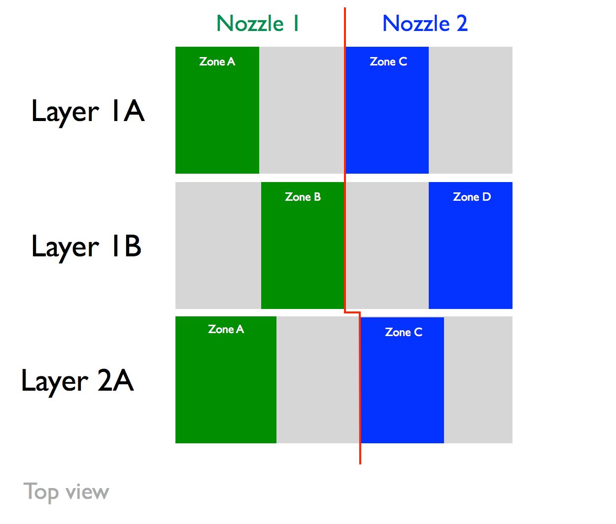
@o_lampe No, the zones are in a row, not a square. See image. This is the top view of the zones (perpendicular to Z axis). Nozzle 1 would always left of the red line in Zone A or B, and Nozzle 2 would always be to the right of the red line. So the sequence is:
- Layer 1A prints: Nozzle 1 stays in Zone A, Nozzle 2 stays in Zone C.
- Layer 1B prints: Nozzle 1 stays in Zone B, Nozzle 2 stays in Zone D.
- Layer 2A prints: In Layer 2A, the zones shift slightly so that there is an interweaving joint between layers instead of a butt joint (hence shift of the red line).
- Layer 2B prints.
- Layer 3A prints: In Layer 3A, the zones shift slighty back to the same positions in Layer 1, and the process loops.
Nozzle 1 would move to the left when not printing while Nozzle 2 would move to the right. As long as the toolhead is narrower than the adjacent zone, and each "half" layer is finished before printing the other "half" layer, collision is not possible.
How difficult would it be to script something like this? It seems it would be much simpler than true collision avoidance collaboration, particularly if the single part was divided into 4 parts (one for each zone) with the interweaving layers in CAD.
-
@loddie I think openScad is a good way to split an .stl object in four sections, even with interweaving in z-direction.
The slicer has to create two files, one for each nozzle. There are already ways to tell a slicer it is a dual-"color" object (eg. zone a + zone b)
You have to create two tools for each nozzle (although they are technically identical)
This way you make sure, the zones print in the right order.The only difficulty is to synchronize both gcode-streams when:
- changing zones or start the next layer
- wait for the other stream to finish.
The second option is easier to implement by adding some conditional tool-change gcode, but it can cause oozing.
-
@o_lampe said in Multiple Motion System:
openScad
Thanks! I'm not familiar with openScad but am quite proficient with Fusion360. It seems slicing the model is the easy part. As you mention, it the synchronization that I am not sure about.
-
@loddie The good thing about openScad is, that you can use parameters. You only have to write the script once and can later adapt it to a new object.
(things like first layer height, # of perimeters, layer height and layer width )
Just out of curiosity I'll try to write a script, although I don't have a printer to test it. -
Re: synchronizing two gcode streams
@chrishamm
Would it be possible to simulate two gcode files and filter out their layer-times?
It would then be possible to postprocess the files and change printspeed multiplier (M220) for each layer to make them match. -
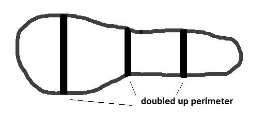
@loddie Are you aware that splitting the object will cause twice as many perimeters at places you'd probably won't like to see any...
At every zone-border and between the two nozzles
Quick hand drawing
-
@o_lampe Good idea! Some have mentioned that different speeds results in difference in print quality if not appearance. Perhaps this could be addressed by having the outer wall speeds, the same, but have differing infill speeds.
-
@o_lampe I had not thought of that. Thank-you for pointing it out.
This application would be TPU, which I have yet to print with (mainly ABS/PLA). Does TPU require a perimeter for an object the size on an infill? If so, seems the G-Code would need to be edited. Or, perhaps the perimeter could be designed into the CAD file so that it exists for adhesion, but eliminate the perimeter from the slicer settings.
-
@loddie TPU sticks pretty good to the bed, so It would be possible to print without perimeter.
But then the interweaving part would probably look messy, because infill-slicing is a different beast.
Do you want to print the first layer(s) solid or start with the infill right away?There is another option to match zone/layer-times.
If you split the object by equalizing the surface areas, they would automatically have the same print duration.
The design would have to be uniform along the z-axis for that.
I'm not sure if a surface-calculation tool exists amongst slicers. -
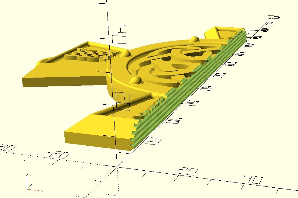
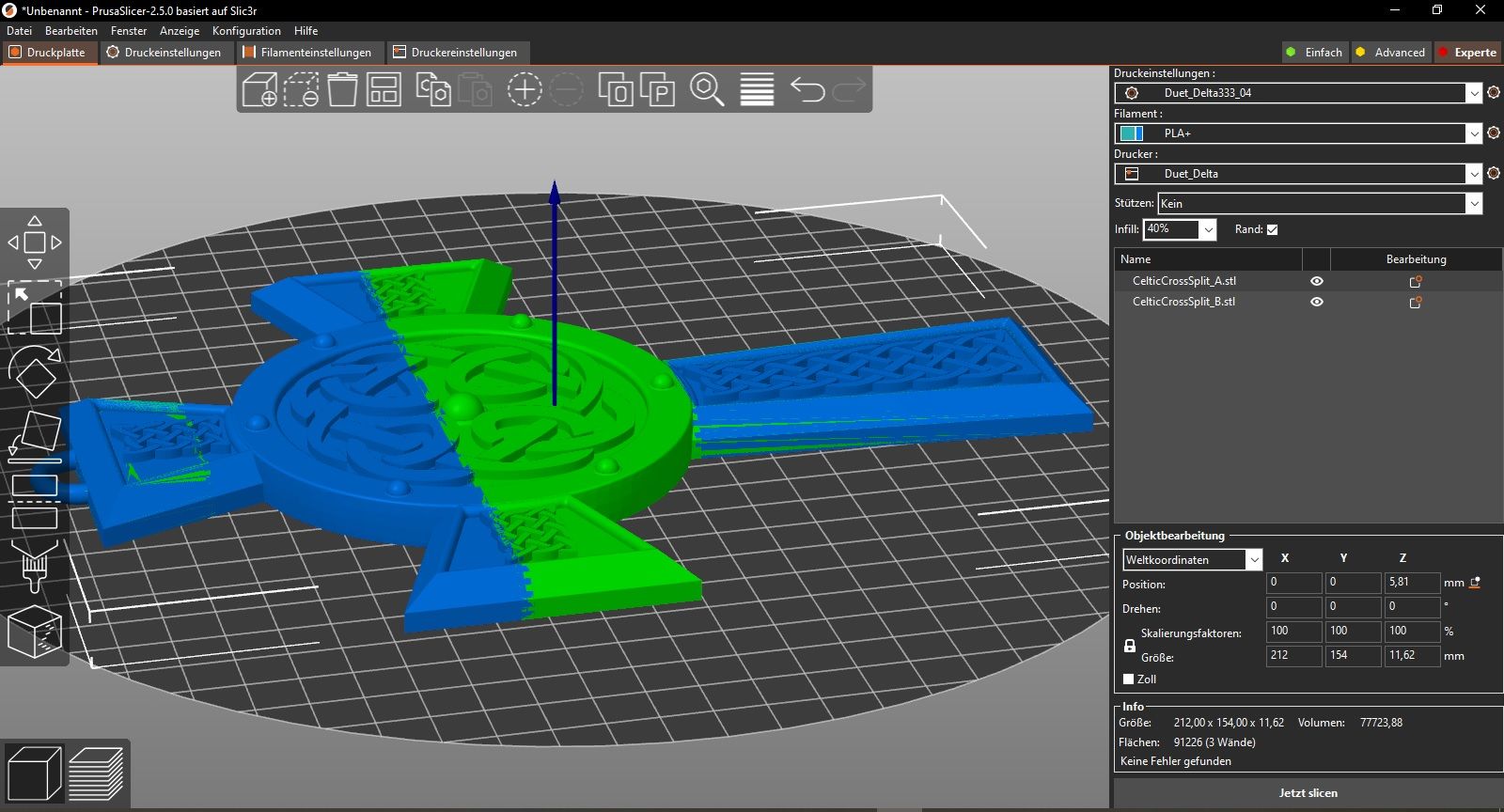
Just a little heads-up about the STL-splitting.
It's a bit tedious, but doable with OpenScad. Maybe fusion360 or other CAD programs have better options, but it's a starting point.
I've chosen a coarse interweaving pattern, which is 3 layers high.
Here are screenshots of a split object and how it looks in PrusaSlicer.