Mesh bed leveling - probe says it can't reach the position
-
Hi all,
I've been trying to setup mesh bed leveling on my duet2 for half a day now and I can't get it to probe the last row no matter what I do. I suspect I'm making some simple mistake so if someone would look at my config, I'd appreciate it.
config.g
; Configuration file for Duet WiFi (firmware version 2.03)
; executed by the firmware on start-up
;
; generated by RepRapFirmware Configuration Tool v2.1.2 on Tue Nov 19 2019 11:51:11 GMT+1100 (Australian Eastern Daylight Time)

; General preferences
G90                                         ; send absolute coordinates...
M83                                         ; ...but relative extruder moves
M550 P"HEVO"                                ; set printer name

M667 S1                                     ; select CoreXY mode

; Network
M552 S1                                     ; enable network
M586 P0 S1                                  ; enable HTTP
M586 P1 S1                                  ; enable FTP
M586 P2 S0                                  ; disable Telnet

; Drives
M569 P0 S1                                  ; physical drive 0 goes forwards
M569 P1 S1                                  ; physical drive 1 goes forwards
M569 P2 S1                                  ; physical drive 2 goes forwards
M569 P3 S1                                  ; physical drive 3 goes forwards
M584 X0 Y1 Z2:4 E3                          ; set the second E to be Z2
M671 X437.0:-39 Y0:0 S4  ; Set the Z motor relative locations
M350 X16 Y16 Z16 E16 I1                     ; configure microstepping with interpolation
M92 X160.00 Y160.00 Z400.00 E409.00          ; set steps per mm
M906 X800 Y800 Z800 E850 I30                ; set motor currents (mA) and motor idle factor in per cent
M84 S30                                     ; Set idle timeout

; Speed - M556 and M203 in mm/m and M203 and M204 in mm/s
M566 X500 Y500 Z60 E800     ; set maximum instantaneous speed changes (mm/min)
M203 X30000 Y30000 Z600 E10000 ; set maximum speeds (mm/min)
M201 X9000 Y9000 Z600 E10000        ; set accelerations (mm/s^2)
M204 P800 T4000			; Set printing and travel accelerations

; FEEDRATE CONVERSIONS
	; 20mm/s = F1200
	; 70mm/s = F4200
	; 120mm/s = F7200
; mm/s * 60 = mm/m
; mm/m / 60 = mm/s


; Axis Limits
M208 X0 Y-49 Z0 S1                            ; set axis minima
M208 X366 Y358 Z360 S0                      ; set axis maxima

; Endstops
M574 X1 Y1 S3                               ; set endstops controlled by motor stall detection
M574 Z1 S2                                  ; set endstops controlled by probe

; Z-Probe
M307 H3 A-1 C-1 D-1                         ; disable heater on PWM channel for BLTouch
M558 P9 H5 F250 T12000                      ; set Z probe type to bltouch and the dive height + speeds
G31 P500 X58 Y-38 Z2.28                       ; set Z probe trigger value, offset

; Heaters
M305 P0 T100000 B3950 R4700                 ; set thermistor + ADC parameters for heater 0
M143 H0 S120                                ; set temperature limit for heater 0 to 120C
M305 P1 T100000 B4725 C7.060000e-8 R4700    ; set thermistor + ADC parameters for heater 1
M143 H1 S300                                ; set temperature limit for heater 1 to 280C

; Fans
M106 P0 S0 I0 F500 H-1                      ; set fan 0 value, PWM signal inversion and frequency. Thermostatic control is turned off
M106 P1 S1 I0 F500 H1 T45                   ; set fan 1 value, PWM signal inversion and frequency. Thermostatic control is turned on
M106 P2 S1 I0 F500 H1 T45                     ; set fan 2 value, PWM signal inversion and frequency. Thermostatic control is turned off

; Tools
M563 P0 D0 H1 F0                            ; define tool 0
G10 P0 X0 Y0 Z0                             ; set tool 0 axis offsets
G10 P0 R0 S0                                ; set initial tool 0 active and standby temperatures to 0C

; Custom settings are not defined
; ############################
; 11 - MISCELLANEOUS
; ############################

M501                                               	; Load saved parameters from non-volatile memory
T0                                                 	; Select first tool
The mesh bed macro I'm using to run mesh bed leveling
G28 X ;home x
G28 Y ;home y
G28 Z ; home Z last

M557 X58:394 Y-38:320 S40 ; sets the X and Y Grid dimensions with a spacing of 40.


G29 S0 ; Run probing sequence as defined in M557 above and save height map to SD.
M374 ; Save the height map explicitly.

G1 F12000 X5 Y5 ; move the carriage back to
bed.g for if its important
; bed.g ; called to perform automatic bed compensation via G32 ; ; generated by RepRapFirmware Configuration Tool v2.1.2 on Tue Nov 19 2019 11:51:10 GMT+1100 (Australian Eastern Daylight Time) G28 ;home ; this is the probe locations, not the nozzles. ; consider the probe offsets. ; ignores endstops. G30 P0 X58.0 Y152 H0 Z-99999 G30 P1 X366.0 Y152.0 H0 Z-99999 S2 G28 Z ; home Z again to help with bed sag. G29 S1; loads the height map -
I can't see a problem with those files. I would expect the first row to be at Y=-38 and the last at Y=282, which should both be reachable by a probe with a Y offset of -38.
After running mesh probing, please run the following commands without parameters to check that the values set correspond to the ones in config.g and your macro: M208, M557, G31.
-
Output of M208
Axis limits X0.0:366.0, Y-49.0:358.0, Z0.0:360.0M557
Grid: X58.0:394.0, Y-38.0:358.0, radius -1.0, X spacing 40.0, Y spacing 40.0, 90 pointsG31
Current reading 0, threshold 500, trigger height 2.28, offsets X58.0 Y-38.0I posted the wrong meshbedlevel.g file, I had been changing it while trying to make it work. The one that is causing errors is:
G28 X ;home x
G28 Y ;home y
G28 Z ; home Z last

M557 X58:394 Y-38:358 S40 ; sets the X and Y Grid dimensions with a spacing of 40.


G29 S0 ; Run probing sequence as defined in M557 above and save height map to SD.
M374 ; Save the height map explicitly.

G1 F12000 X5 Y5 ; move the carriage back to the start
The errors in the console are:
M98 P"0:/macros/MeshLevel.g"
Warning: Skipping grid point (378.0, 322.0) because Z probe cannot reach it
Warning: Skipping grid point (338.0, 322.0) because Z probe cannot reach it
Warning: Skipping grid point (298.0, 322.0) because Z probe cannot reach it
Warning: Skipping grid point (258.0, 322.0) because Z probe cannot reach it
Warning: Skipping grid point (218.0, 322.0) because Z probe cannot reach it
Warning: Skipping grid point (178.0, 322.0) because Z probe cannot reach it
Warning: Skipping grid point (138.0, 322.0) because Z probe cannot reach it
Warning: Skipping grid point (98.0, 322.0) because Z probe cannot reach it
Warning: Skipping grid point (58.0, 322.0) because Z probe cannot reach it
What I am trying to achieve is that the probes last probe row will be along a nozzle position of Y358 which I understand should have the probe at Y320. Y358 is the maximum Y position before the carriage will collide with the frame.
-
The M557 coordinates give the bed position to be probed. As you have an offset Z probe, the nozzle Y position will be 38mm higher than the Y bed coordinate to be probed. So the highest Y coordinate you can probe is 38mm less than the max Y specified in your M208 command, so 320. That explains the messages when your M557 command goes up to Y358 and it tries to probe at Y322.
Duet WiFi hardware designer and firmware engineer
Please do not ask me for Duet support via PM or email, use the forum
http://www.escher3d.com, https://miscsolutions.wordpress.com -
@dc42 said in Mesh bed leveling - probe says it can't reach the position:
The M557 coordinates give the bed position to be probed. As you have an offset Z probe, the nozzle Y position will be 38mm higher than the Y bed coordinate to be probed. So the highest Y coordinate you can probe is 38mm less than the max Y specified in your M208 command, so 320. That explains the messages when your M557 command goes up to Y358 and it tries to probe at Y322.
Hi David,
Would it be possible you could have a look at my similar thread regarding mesh leveling on Printbite with the IR probe?
I asked a question on what's working or not, and it would be handy to know before logging into Paypal...
-
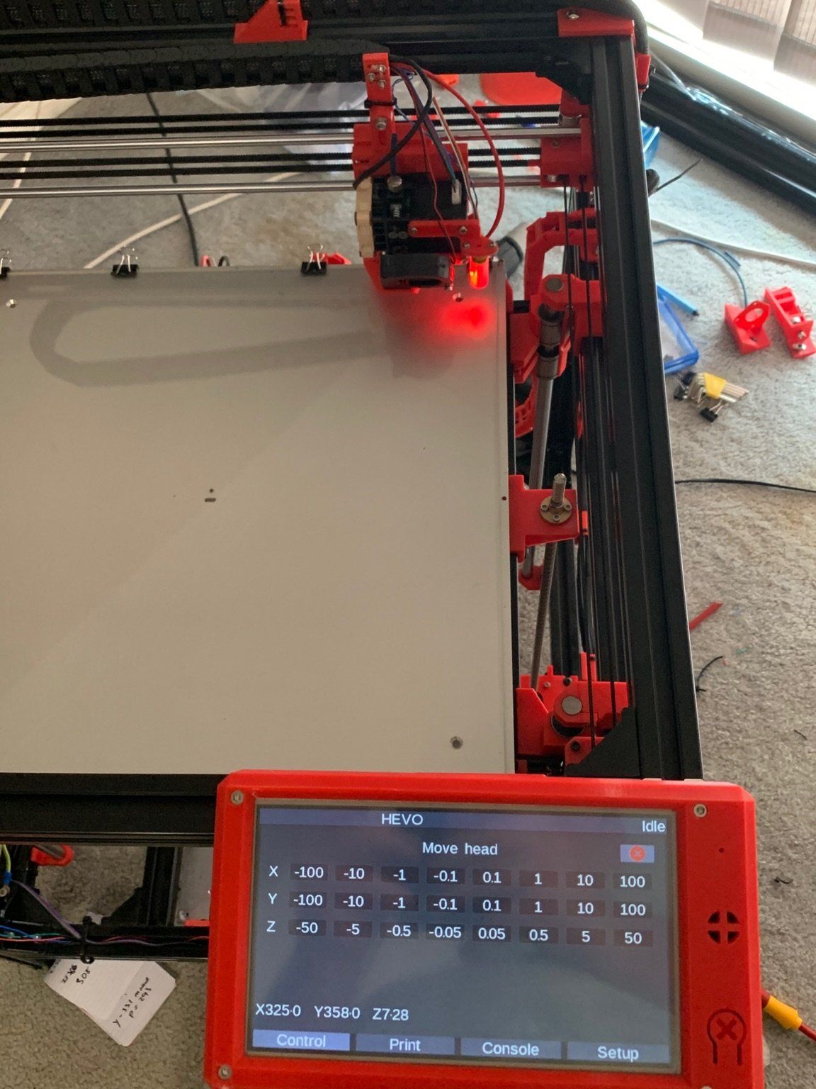
@dc42 Right, thanks. I guess I still don't get how I can have the probe probe at the back of the print bed.
With the maxima set to Y358 using M308, the highest value I can have with M557 for Y is Y320.
If I adjust the maxima for the Y axis to Y396 so that M557 will accept Y358, I assume this will let the carriage crash into the frame as it can't go that far.
The photo below has the probe in the position of the row I want to probe so it can physically reach.
-
i was dealing with this same problem too, The M557 command is using printer absolute cordinates without the tool offset, which is quite confusing. So if you want the points to be correct, you have to add/subtract the tool offsets to it. Kinda hard to explain so ill show mine
M557 X55:230 Y30:210 S40 ; define mesh grid
G10 P0 X-35 Y-13 Z-0.5 ;set tool 0 axis offsets
G31 X55 Y0 Z2 P25 ; sets z probe offests and sets activation valueso the nozzle is X -35 and the probe is X+60 from that. I want my first point to be around 20mm from the edge of the bed
so my first probe points is gonna be X55 as its X 60-35+20 = 55.
then just repeat for all axis and the end.