A4988 Shield Board to 1XD
-
Hello,
I'm struggling to correctly wire an A4988 Sheild to my 1XD.
Here was my attempt which didn't seem to work. Do I need anything going to the S row at all? I figured since microstepping is in the firmware I didn't need to. I'm powering my 1XD with 24V and using the OUT1 to power this sheild, those wires are not shown
-
 undefined JRCL marked this topic as a question
-
@JRCL it will be the enable signal. It’s always the enable signal! Try disconnecting it, and see if it works.
Ian
Bed-slinger - Mini5+ WiFi/1LC | RRP Fisher v1 - D2 WiFi | Polargraph - D2 WiFi | TronXY X5S - 6HC/Roto | CNC router - 6HC | Tractus3D T1250 - D2 Eth
-
@JRCL I think you risk damaging the 1XD with that connection, because you have probably shorted some of the 1XD outputs to ground. To give further advice I will need to know what the S, V and G letters on that board signify.
Duet WiFi hardware designer and firmware engineer
Please do not ask me for Duet support via PM or email, use the forum
http://www.escher3d.com, https://miscsolutions.wordpress.com -
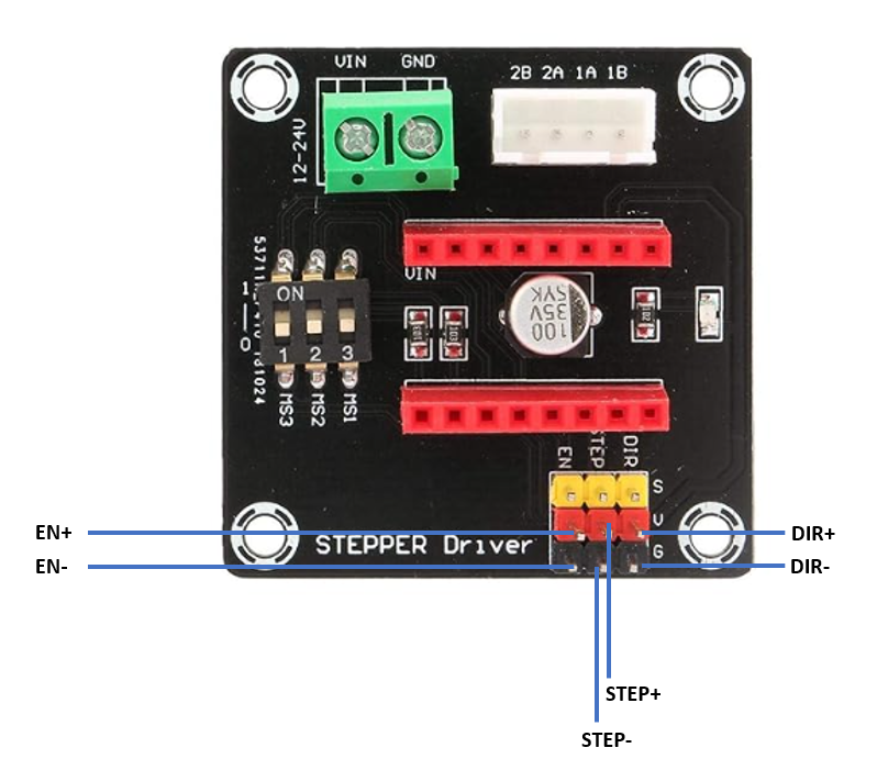
@dc42 I wish the documentation was better but what I've found is S is micro stepping/signal, V is vin, and G is GND. If that doesn't make sense then I'm unsure and sounds like I should consider getting a different board
-
@droftarts tried disconnecting both EN pins individually and together and didn't seem to make a difference
-
@JRCL ah, I hadn't noticed you had connected between V and GND. I have the exact same driver board, though I haven't actually ever needed to get it working! I've just checked it with my meter; the three V pins are connected together, and are NOT connected to the VIN input screw terminal, and the three GND pins are connected together, and are connected to the GND terminal. So I don't think you have put VIN voltage through the 1XD.
I found the following couple of wiring diagrams online:
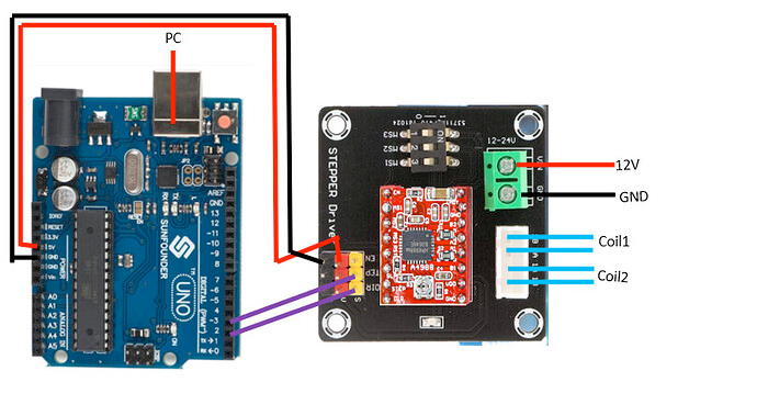
They both show pretty much the same thing. 5V and GND are supplied from the controller, connecting to the V and GND pins. The S (signal) pins are connected are connected to pins that switch to ground on the controller. For the 1XD, you want to wire it as shown in the 'single ended connection' here https://docs.duet3d.com/Duet3D_hardware/Duet_3_family/Duet_3_Expansion_1XD#external-stepper-connection
You probably don't need to connect to the ground pins, but if you have a spare GND pin on the 1XD, it won't hurt.While it's a slightly different version of the board, also see https://docs.duet3d.com/en/User_manual/Connecting_hardware/Motors_connecting_external#examples
Just in case you are worried, the A4988 is compatible with 3.3V and 5V logic supply: https://www.pololu.com/file/0J450/a4988_DMOS_microstepping_driver_with_translator.pdfIan
Bed-slinger - Mini5+ WiFi/1LC | RRP Fisher v1 - D2 WiFi | Polargraph - D2 WiFi | TronXY X5S - 6HC/Roto | CNC router - 6HC | Tractus3D T1250 - D2 Eth
-
Based on the wiring diagrams posted by @droftarts, the following should work:
- Connect Step+, Dir+ and En+ from the 1XD to the corresponding S pins on the shield board
- Connect one of the G pins to ground on the 1XD
- Connect one of the V pins to +5V on the 1XD.
Duet WiFi hardware designer and firmware engineer
Please do not ask me for Duet support via PM or email, use the forum
http://www.escher3d.com, https://miscsolutions.wordpress.com -
@droftarts thanks for doing some digging and finding those and @dc42 for summarizing. I gave it a try and the board's power status LED is on at least. However, I still can't get the stepper to move. I tested the leads with a multimeter and different controller to confirm it was wired properly to the shield. Any other thoughts on wiring setups to try? Perhaps it got shorted?
-
Connect Step+, Dir+ and En+ from the 1XD to the corresponding S pins on the shield board
I think it should be: connect Step-, Dir- and En- from the 1XD to the corresponding S pins on the shield board. That's how the single ended wiring is shown in the 1XD documentation, and the Arduino Uno diagrams show a connection to the PWM- pins.
And you may need to play around with the enable signal, either invert it (M569 R0 or R1) or try disconnecting it, as most drivers are enabled by default. It's always the enable signal! (Apart from everything else!)
How is the drive configured in the M569 command in config.g? You will need to set the timing with the T parameter; try something like
M569 P40.0 S0 R1 T5:5:10:10How have you set the microstepping switches? You can't set microstepping for the drive in config.g.
Have you set the stepper driver current by setting the reference voltage on the trimpot on the A4988 driver?Ian
Bed-slinger - Mini5+ WiFi/1LC | RRP Fisher v1 - D2 WiFi | Polargraph - D2 WiFi | TronXY X5S - 6HC/Roto | CNC router - 6HC | Tractus3D T1250 - D2 Eth
-
@droftarts I did try connecting Step-, Dir- and En- but did not play around with the enable or R parameter in M569. However, I definitely didn't know that T has to be set with the 1XD. I also didn't know you couldn't configure the micro stepping in config.g so I had left the switches on full step. Seems I missed some readings in that external steppers page.
I've got some things to test and will report back. Quick aside, I wanted to add one more stepper to my machine but I had already used all on my MB6HC and on my 1LC. I figured daisy chaining this 1XD in would be the best way to add one but it's becoming more of a project than expected. Is there a better way to do this hardware wise or was this the right choice for one more stepper and endstop.
-
@droftarts Tried using both + sets and - sets. Tried dropping the enable signal pin on both as well as both with R1 and R0. Added the T parameter but still couldn't get it to work. The trim pot is tuned and microstepping switches are set to 1/16th. Maybe I'm missing something in my config. Including that too:
; Enable network G4 S5 ;wait for board to start if {network.interfaces[0].type = "ethernet"} M552 P192.168.1.14 S1 else M552 S1 ;General Prefrences G90 ; send absolute coordinates... M83 ; ...but relative extruder moves M550 P"RL1 V3" ; set printer name M669 K1 ; switch to CoreXY mode ; Drives M569 P0.0 S1 ; X motor runs M569 P0.1 S0 ; Y motor runs M569 P0.2 S1 ; Z1 motor runs M569 P0.4 S1 ; Z2 motor runs M569 P0.5 S1 ; Z3 motor runs M569 P20.0 S0 ; E moves M569 P0.3 S0 ; U motor runs M569 P40.0 R1 T5:5:10:0 ; V motor runs M207 S1.5 F7200 Z0.2 M584 X0.0 Y0.1 Z0.2:0.4:0.5 E20.0 U0.3 V20.0 ; Set drive mapping M350 X16 Y16 Z16 E16 U16 I1 ; configure microstepping with interpolation M92 X80.00 Y80.00 Z400.00 E685.37234 U100 V80 ; set steps per mm M566 X900.00 Y900.00 Z60.00 E300 U900.00 V900 ; set maximum instantaneous speed changes (mm/min) M203 X6000.00 Y6000.00 Z180.00 E7200 U17000.0 V6000 ; set maximum speeds (mm/min) M201 X500.00 Y500.00 Z20.00 E3000 U500.0 V500 ; set accelerations (mm/s^2) M906 X800 Y800 Z800 U3800 V800 I30 ; set motor currents (mA) and motor idle factor in per cent M906 E1200 I10 ; extruder current and idle factor M572 D0 S0.02 ; pressure advance-to be calibrated M84 S30 ; Set idle timeout ; Axis Limits M208 X0 Y0 Z-1 U0 V0 S1 ;set axis minima M208 X100 Y100 Z38.45 U330 V100 S0 ;set axis maxima M671 X-67.2193:182.5338:182.5338 Y54.4915:-72.3045:181.2875 S2 ; position of leadscrew/bed pivot point at front left, rear middle and front right ; Endstops M574 X1 S1 P"20.io1.in" ; configure switch-type (e.g. microswitch) endstop for low end on X via pin io0.in M574 Y2 S1 P"20.io2.in" ; configure switch-type (e.g. microswitch) endstop for high end on Y via pin io1.in M574 Z2 S1 P"0.io3.in+0.io4.in+0.io5.in" ; configure switch-type (e.g. microswitch) endstop for high end on Z M574 U2 S1 P"0.io6.in" ; configure switch-type (e.g. microwswitch) endstop M574 V1 S1 P"40.io1.in" ;configure switch endstop for low end ; Z-Probe M950 S0 C"20.io0.out" ; create servo pin 0 for BLTouch (use IO_4/5/7 for 6HC) M558 P9 C"20.io0.in" H5 F120 T6000 ; set Z probe type to bltouch and the dive height + speeds G31 P500 X-19.14 Y0 Z4.242 ; set Z probe trigger value, offset and trigger height M557 X0:80 Y12:100 P3 ; define mesh grid ; Heaters M308 S0 P"temp0" Y"thermistor" T100000 B3950 ; configure sensor 0 as thermistor on pin temp0 M950 H0 C"0.out0" T0 ; create bed heater output on out0 and map it to sensor 0 M307 H0 R0.075 K0.161:0.000 D3.07 E1.35 S1.00 B0 M140 H0 ; map heated bed to heater 0 M308 S1 P"20.temp0" Y"thermistor" ; configure sensor 1 as thermistor on pin temp1 M950 H1 C"20.out0" T1 ; create nozzle heater output on out1 and map it to sensor 1 M307 H1 R4.585 K0.421:0.683 D3.75 E1.35 S1.00 B0 V24.2 ; disable bang-bang mode for heater and set PWM limit M143 H1 S280 ; set temperature limit for heater 1 to 280C ; Fans M950 F0 C"20.out1" Q500 ; create fan 0 on toolboard out1 and set its frequency M106 P0 S1 H-1 ;T50 ; set fan 0 value. Thermostatic control is turned on M950 F1 C"20.out2" Q500 ; create fan 1 on toolboard out2 and set its frequency M106 P1 S0 H-1 ; set fan 1 value. Thermostatic control is turned off ;Relays M950 P9 C"40.out0" ;external stepper controller power M42 P9 S1 ;turn on M950 P2 C"0.io_7.out" ;Heater M42 P2 S0 ;Start in off position M950 P3 C"0.io_1.out" ;Clamps FWD M42 P3 S0 ;Start in off position M950 P4 C"0.io_8.out" ;Clamps REV ;M42 P4 S0 ;Start in off position ;M950 P5 C"0.io2.out" ;IPV DWN ;M42 P5 S0 ;Start in off position ;M950 P6 C"0.out9" ;IPV UP ;M42 P6 S0 ;Start in off position M950 P5 C"0.out2" ;Chamber Pressure M42 P5 S0 ;Start closed M950 P6 C"0.out1" ;IPV Direction M42 P6 S0 ;Start in down position M950 P7 C"0.io_0.out" ;Inlet Valve M42 P7 S0 ;Start closed M950 P8 C"0.out3" ;Emergency Valve M42 P8 S0 ;start closed ;Tool Definitions M563 P0 D0 H1 F0 ; tool 0 uses extruder drive 0 and heater 1. Fan 0 and Fan 1 are mapped to tool 0 G10 P0 X0 Y0 Z0 ; set tool 0 axis offsets G10 P0 R0 S0 ; set initial tool 0 active and standby temperatures to 0C ; Epilogue M556 S100 X0 Y0 Z0 ; Put your axis compensation here M912 P0 S0 ; Put your CPU temperature sensor correction here M501 ; load saved parameters from non-volatile memory M911 S10 R11 P"M913 X0 Y0 G91 M83 G1 Z3 E-5 F1000" ; set voltage thresholds and actions to run on power loss T0 -
@JRCL you haven’t defined an axis for the driver on the 1XD; it looks like you defined the 1LC twice, to E and V axis:
M584 X0.0 Y0.1 Z0.2:0.4:0.5 E20.0 U0.3 V20.0Ian
Bed-slinger - Mini5+ WiFi/1LC | RRP Fisher v1 - D2 WiFi | Polargraph - D2 WiFi | TronXY X5S - 6HC/Roto | CNC router - 6HC | Tractus3D T1250 - D2 Eth
-
@droftarts There it is! With this change, the stepper finally started working. If I wire to + set then R0 works and if I wire to - R1 is needed.
-
undefined JRCL has marked this topic as solved