Smart Effector with Toolboard and extruder
-
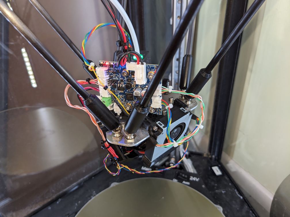
Why
I like my delta (https://forum.duet3d.com/topic/25575/a-delta-with-colourful-lights) but I was never really happy with the bowden. It's just so much more aggro than the direct extruder on my bedslinger - I never got it working well with (modestly) larger nozzles - 0.8mm.
The two signal wires and two power wires that CAN bus offers looks ideal for a delta. There's been talk of a CAN bus smart effector for years, but it doesn't look like it's going to happen (for the latest I recall see https://forum.duet3d.com/topic/34657/combined-smart-effector-and-tool-board-for-delta-printers - I interpret this as several people very keen for such a board, but probably not enough people to make it happen).
I wasn't terribly happy with the cooling I had on my smart effector, so I wanted to boost that.
Therefore, I decided to stop waiting and figure out how to put a toolboard, extruder and smart effector on my delta's toolhead.
I've occasionally talked to people with similar ideas. Most recently and special mention to @Mr-Crispin, who shared his solution and even sent STLs. He spurred me to think a bit more creatively about configuration than I had been (and also to contemplate surgery on the smart effector board).
What
I have a smart effector v2, a Revo Micro, wanted to use an Orbiter2 (that's what is on my bedslinger and I'm happy), normal toolboard is cheaper than the roto one (and my bedslinger has a normal one so maximises commonality of crimps etc). That defines the components.
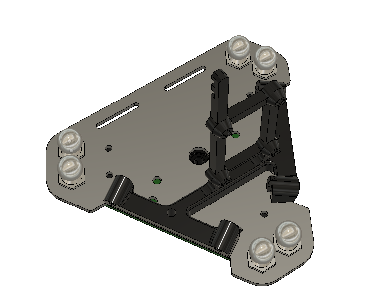
Some Fusion-360-ing gave me
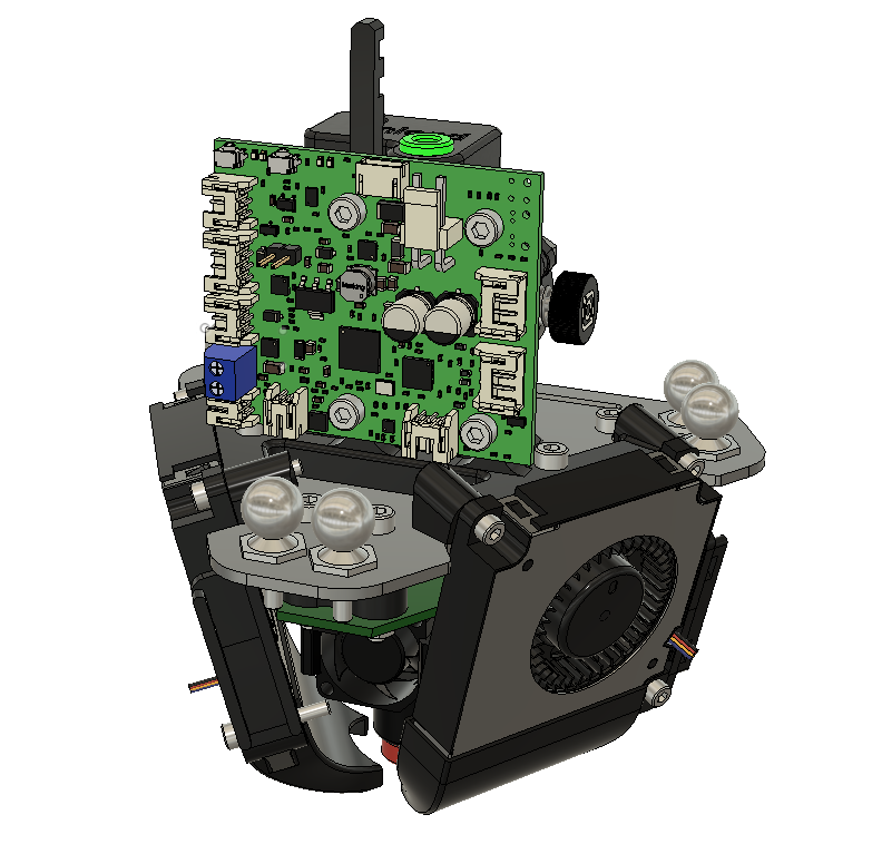
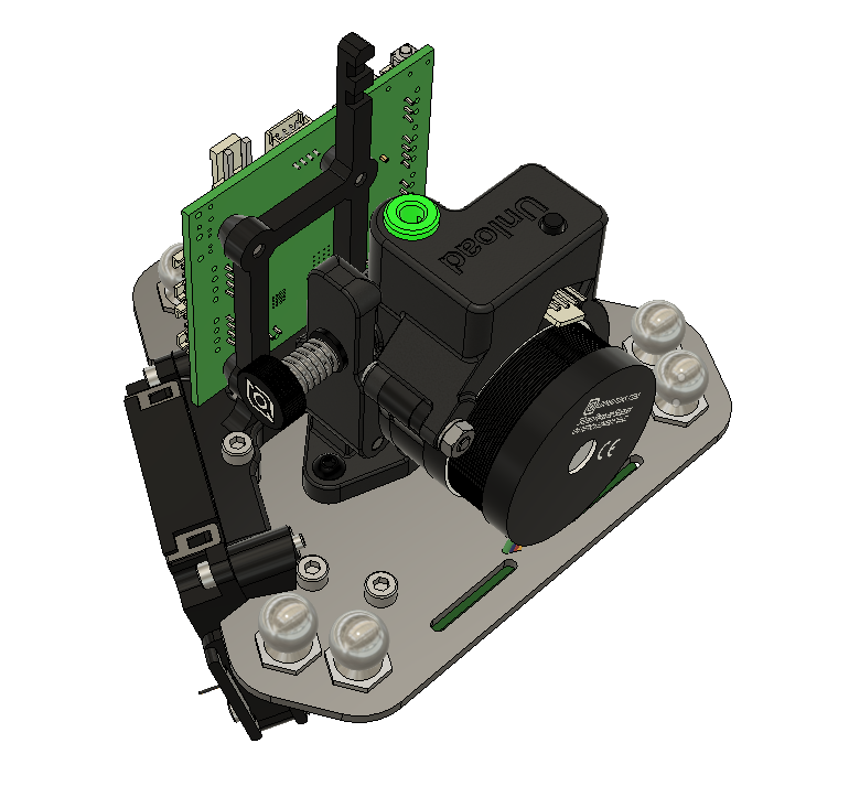
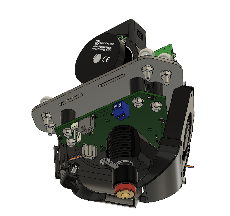
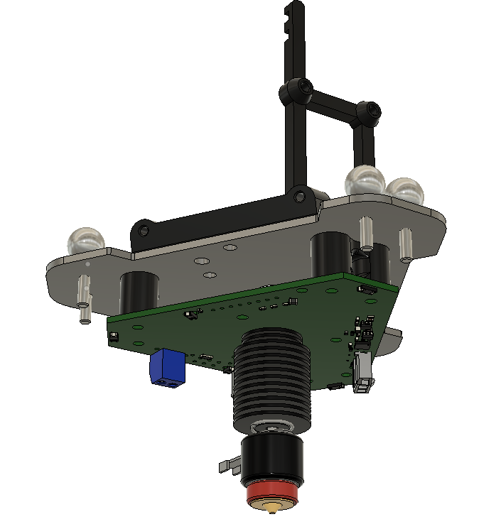
Essentially, it's a 2mm laser-cut aluminium plate (1.5mm would have been fine) that puts the magballs at 80mm centres, there's a printed frame above the plate to hold the toolboard and two 50x50x10 4-wire centrifugal fans, and there are 12mm high printed spacers below the plate that hold the smart effector. The extruder bolts direct to the plate. Toolboard and fan bolts just self-tap into the plastic of the printed parts (my bedslinger mostly has brass inserts, but rarely gets dismantled so I didn't bother when building this).
I have taken the two connectors off the top of the smart effector and soldered wires direct to the effector pcb (with the toolboard connectors on the other end). The 1x8 signal connector was really difficult (the pins are very tight in the holes) and if I did it again I might just cut away the plastic and solder to the pins. The 2x3 power connector was much easier. The connectors are still in the Fusion model (just invisible) so you can switch them back on. There are also some right-angle ones in the model because I experimented with that.
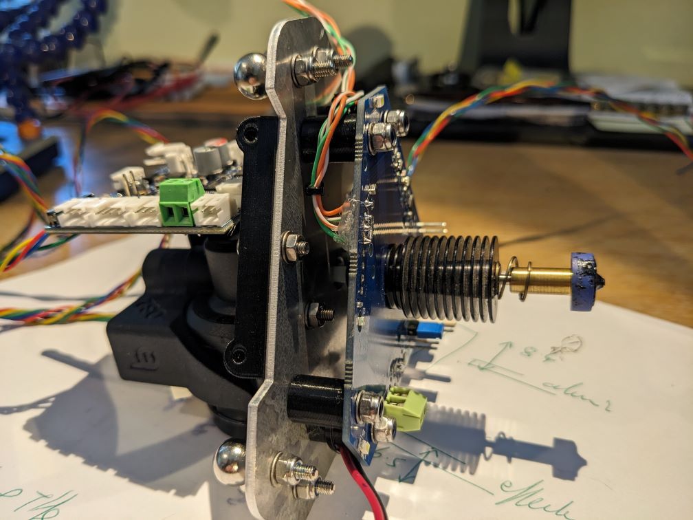
It's now only the hotend fan that's powered through the 2x3 - I do that so the LEDs light. I have four of the eight signal wires for the z-probe (though you can't program it through the toolboard, so one of those is redundant), and everything else bypasses the smart effector and goes direct to the toolboard (i.e. heater, thermistor and print cooling fans don't go via the effector board).
If you didn't want to take connectors off the board you'd need taller spacers. That would necessitate adjusting the fans angle and fan ducts.
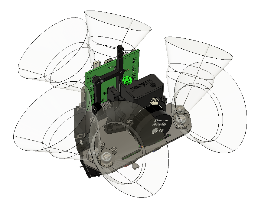
The Fusion model has the envelopes of the arms / rods in it. Rod angles were calculated in excel for 18 head positions and the envelope is 'eyed in' around them. If you go into a 'magball arm' in Fusion the 'arm range' component shows the individual arm positions the envelope is generated from. There are some tight clearances - a different geometry printer might not work with this exact design.
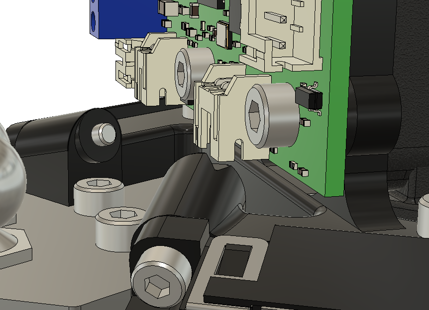
On the topic of clearances, there’s not enough at IO2. In fact, the upper frame is notched around the IO2 socket. When designing, I didn't plan to use this connector, but then I wanted another input, and then I wanted a source of 5V (to put pullup on a fan control line - see https://forum.duet3d.com/topic/35576/trouble-with-delta-fan), so I ended up using a cut-down plug that only has those two positions left in it).
The umbilical (PTFE, signal wires, power wires) now fits in nominal 4mm braided sleeve.
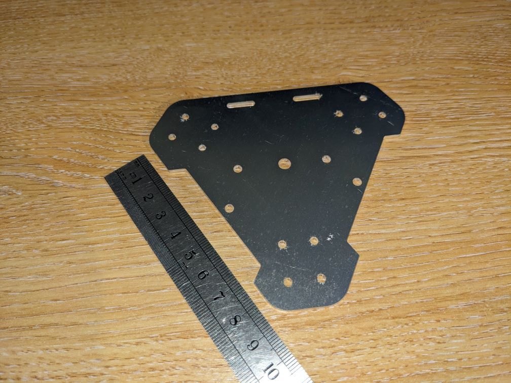
Obviously I need new carriage plates with 80mm spacing. They too are laser cut 2mm aluminium. My laser-cutting was by https://www.lasermaster.co.uk/ and I remain a very happy customer - their prices are reasonable even when I've ordered a single small piece. I got two complete sets (two effector plates, six carriage plates) and it cost me £43.88 including delivery and VAT, and they took about a week from me emailing the dxfs to the plates appearing at my front door. (I got two sets in anticipation of having forgotten something critical and needing to make corrections manually, thus giving me a spare in case my hand was not as steady as their laser.)
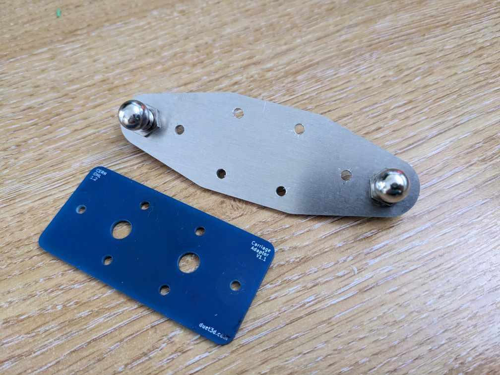
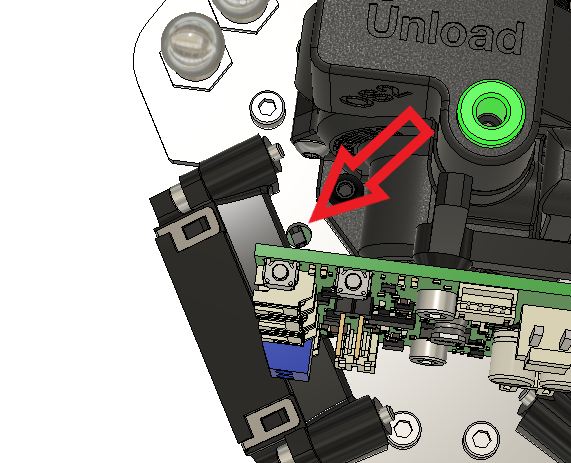
I've adjusted the effector plate design slightly since making it, though there will probably never be a 'next time'. The holes for M3 bolts are nominal 2.9mm diameter, but some of the bolts are fractionally looser than I'd like - next time I'd do 2.8 probably and plan on opening them slightly. I didn't make the central filament/PTFE hole big enough, but just enlarged it with a drill. I've lengthened the slots at one edge (which are for cable-tying on the Revo's dangling dongle fan power adaptor). The main functional annoyance which I've addressed is to add a hole allowing sightline to the smart effector indication LED - I can't see it with my design as manufactured.
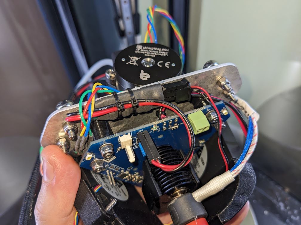
My delta has two power supplies - a 12V psu is on continuously, which generates 5V for the Pi and the MB6HC via a DC-DC POL module and drives enclosure illumination LEDs. The 24V 'heavy lifting' supply is switched on when the printer is driving motors or heaters. That gives a bit of a headache, because there’s only one pair for power supply to the toolboard, but I want 24V there when operating (my Revo is a 24V, and may as well minimise resistive losses in the wires) so I have it connected to both supplies via Schottky diodes (actually a common cathode dual diode package rated 45V and 10A). The much maligned Revo dangling dongle now comes into its own, because the hotend fan runs at full power whether the toolboard is on 12V or 24V. (Though I did put an extra layer of heatshrink on it before cable-tying it to an aluminium plate).
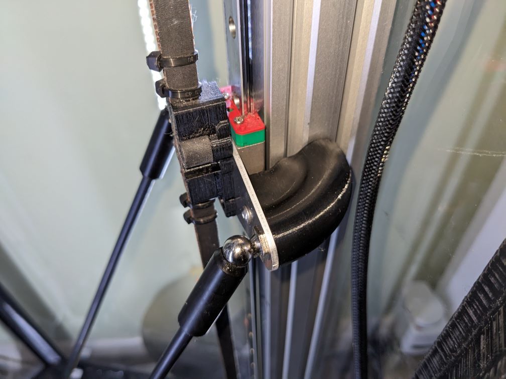
I had problems with the looser longer less restrained umbilical snagging the carriage plate magball bolt. I've printed a cover for the back of the affected carriage plate so the umbilical gets shrugged off.
Files
The Fusion model is about 17MB, which I don't think the forum will like, so I've put it at https://www.astounding.org.uk/ian/temp/Effector_v86.f3z (I'm not sure how long it will stay there though).
In building it I used some other people's components - Duet3D's models of boards, Orbiter from https://www.orbiterprojects.com/ (but one I got some time ago when designing my bedslinger, and it has been tampered with a bit), Revo micro from https://grabcad.com/library/e3d-revo-micro-1, magballs from https://grabcad.com/library/smart-effector-magball-1 (but I simplified it and tampered with materials), fans from Delta's website but I can't remember exactly where (though their model of the actual fan had no impeller or internals, so I added them by scaling from a different fan's model). The rest is by me, note that nuts and bolts are simplified (they are more like the envelope of the part than an accurate modelling). I don't care what anyone does with any of my work, but I take no responsibility for anything that happens.
These are the DXF files of the aluminium plates I'd use now if I assembled another (i.e. with the mods noted above implemented). File names imply two complete sets (as discussed above).
alu_2mm_2thus_effectorplate.dxf
alu_2mm_6thus_carriageplate.dxfThese are some excel files - one is what calculates rod positions for purposes of assembling the rod envelopes for the Fusion model (as discussed above), and the other calculates new delta kinematics definition (i.e. the M665 line) but more interestingly examines the change in error going from 55mm rod centres to 80mm rod centres. Having calculated new delta radius it then does a calculation where for lots of bed positions (7.5mm grid across the bed) it calculates the 'perfect' carriage positions, then applies a random error to each carriage, and calculates the error that arises at the nozzle. It's kind-of a coarse monte-carlo on the error. The 80mm spacing effector is very slightly (negligibly) worse - I end up with a RMS error of about 0.0035mm compared to 0.0033mm for 55mm spacing, if each carriage receives a random error in position of up to 0.5 steps (160 steps/mm so 0.5 steps is 0.0031mm).
delta arms motions.xlsx
delta effector changes.xlsxFWIW the kinematics of 'given a nozzle position, calculate carriage heights' for a linear delta is trivial, but the opposite direction (given carriage positions, calculate where the nozzle is) is rather more involved. I think I've got it right. The calc in the spreadsheet is actually a more general given three arbitrary points in space and an arbitrary distance from each, find the location.
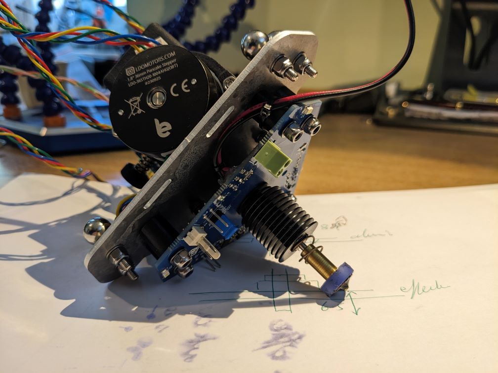
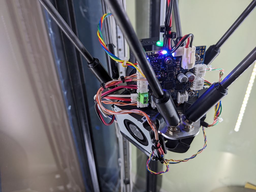
Finally, a few more pictures
