Probe always reads 1000 (deployed)
-
Hi there I'm using a cloned BL touch (3d touch ) I seem to have a problem where it always shows as deployed whether the pin is in or out it does react to the M280 p0 s10 /90 commands and deeply retracts as it should, I thought I had a fault sensor so I tried my genuine CR touch from my Ender and this exactly the same thing.
What's really strange is my old probe which is now damaged which was also a clone of the bltouch, worked perfectly fine unfortunately when I was doing some maintenance my girlfriend stepped on it and broke it

Wiring is as Follows.
Probe side Board Side
Z-Stop (white) -> Z-Probe IN (DUET)
GND (black) -> GND (DUET)
Signal(Yellow) -> PWM5 (DUEX5)
+5v (RED) -> AUX 5v (DUEX5)
GND (BROWN) -> GND (DUEX5); Configuration file for Duet WiFi (firmware version 3) ; Made by Craig Robinson ; General preferences G90 ; send absolute coordinates... M83 ; ...but relative extruder moves M550 P"CraigsMachine" ; set printer name M669 K1 X1:0:0:0 Y1:-1:0:-1 Z0:0:1:0 U0:0:0:1 ;markforged ;M669 K11 X1:0:0:0 Y1:-1:0:-1 Z0:0:1:0 U0:0:0:1 ;markforged new ; Network M552 S1 ; enable network M586 P0 S1 ; enable HTTP M586 P1 S0 ; disable FTP M586 P2 S0 ; disable Telnet M575 P1 S1 B57600 ; enable connection for PanelDue ; Drives M569 P0 S1 ; physical drive 0 goes forwards X is drive 0 M569 P1 S1 ; physical drive 1 goes forwards U is drive 1 M569 P2 S0 ; physical drive 2 goes backwards Y is drive 2 M569 P3 S1 ; physical drive 3 goes forwards E0 is drive 3 M569 P4 S1 ; physical drive 4 goes forwards E1 is drive 4 M569 P7 S1 ; physical drive 7 goes forwards Z1 is drive 5 M569 P8 S1 ; physical drive 8 goes forwards Z2 is drive 6 M569 P9 S1 ; physical drive 9 goes forwards Z3 is drive 7 M569 P10 S1 ; physical drive 10 goes forwards Z4 is drive 8 M584 X0 Y2 U1 Z5:6:7:8 E3:4 ; four Z motors connected to driver outputs 5,6,7 and 8 M350 X16 Y16 Z16 E16:16 U16 I1 ; configure microstepping with interpolation M92 X53.33 Y53.33 Z1600 E981:981 U53.33 ; set steps per mm 981 for corect steps 932 for default(E15090:15090 for 256 microsteps) M566 X1000 Y1000 Z10 E1500:1500 U1000 ; set maximum instantaneous speed changes (mm/min) (tested 500 to 5000) M203 X20000 Y20000 Z500 E4000:4000 U20000 ; set maximum speeds (mm/min) (tested from 1000 to 20000) M201 X1000 Y1000 Z100 E800:8000 U1000 ; set accelerations (mm/s^2) (tested 100 to 2000) M906 X950 Y950 Z950 E950:950 U950 I50 ; set motor currents (mA) and motor idle factor in per cent M84 S30 ; Set idle timeout ;Laser Control ;M452 C"duex.pwm4" R255 F200 ; Enable Laser mode, on exp.heater3, with max intensity being 255, and a PWM frequency of 200 ;Pressure advance ;tested 0.01 upto 0.1 M572 D0 S0.05 ; Axis Limits M208 X-230 Y-230 Z0 U-175 S1 ; set axis minima M208 X175 Y215 Z350 U225 S0 ; set axis maxima ; Endstops M574 X1 S1 P"zstop" ; configure switch-type (e.g. microswitch) endstop for low end on X via pin xstop M574 Y1 S1 P"xstop" ; configure switch-type (e.g. microswitch) endstop for high end on Y via pin zstop M574 Z1 S2 ; configure Z endstop - high end and uses probe M574 U2 S1 P"ystop" M671 X-260:260:260:-260 Y-227:-227:302:302 S10 ; leadscrews positions - Front left, Front right, Rear ; Z-Probe M950 S0 C"duex.pwm5" ;M558 P5 C"^!zprobe.in" H3 F250:30 T6000 ; set Z probe type to bltouch and the dive height + speeds ;M558 P5 C"^!zprobe.in" H3 F250 T6000 A10 R1.25 S0.008 ; Set Z probe type/mode 5. H=Dive Height. F=Speed probe speed, M558 P5 C"^!zprobe.in" H5 F150 T6000 ;A10 R1.25 S0.008 ; Set Z probe type/mode 9. H=Dive Height. F=Speed probe speed, G31 P500 X0 Y-36 Z3.4 ; set Z probe trigger value, offset and trigger height (larger number = Nozzel closer to the bed) M557 X-220:170 Y-220:170 P8:8 ; define mesh grid ; Thermistors definitions M308 S0 P"bedtemp" Y"thermistor" T100000 B4138 ; configure sensor 0 as thermistor on pin bedtemp M308 S1 P"e0temp" Y"thermistor" T100000 B4138 ; configure sensor 1 as thermistor on pin e0temp M308 S2 P"e1temp" Y"thermistor" T100000 B4138 ; configure sensor 2 as thermistor on pin e1temp ; Heaters definitions M950 H0 C"bedheat" T0 ; create bed heater output on bedheat and map it to sensor 0 aka S0 M307 H0 B0 S1.00 ; disable bang-bang mode for the bed heater and set PWM limit M140 H0 ; map heated bed to heater 0 M143 H0 S120 ; set temperature limit for heater 0 to 120C M950 H1 C"e0heat" T1 ; create nozzle heater output on e0heat and map it to sensor 1 aka S1 M307 H1 B0 S1.00 ; disable bang-bang mode for heater and set PWM limit M143 H1 S280 ; set temperature limit for heater 1 to 280C M570 H1 T25 ;Heater temp before raising a fault M950 H2 C"e1heat" T2 ; create nozzle heater output on e1heat and map it to sensor 2 aka S2 M307 H2 B0 S1.00 ; disable bang-bang mode for heater and set PWM limit M143 H2 S280 ; set temperature limit for heater 2 to 280C ; Fans ;M950 F0 C"fan0" Q500 ; create fan 0 on pin fan0 and set its frequency ;M106 P0 S0 H-1 ; set fan 0 value. Thermostatic control is turned off ;M950 F1 C"fan1" Q500 ; create fan 1 on pin fan1 and set its frequency ;M106 P1 S1 H0 T45:100 ; set fan 1 value. Thermostatic control is turned on ;M950 F2 C"fan2" Q500 ; create fan 2 on pin fan2 and set its frequency ;M106 P2 S1 H-1 ; set fan 2 value. Thermostatic control is turned off M950 F0 C"duex.fan3" Q250 ; create fan 3 on pin duex.fan3 and set its frequency M106 P0 S0 L0 X255 H-1 ; set fan 3 value. Thermostatic control is turned off M950 F1 C"duex.fan4" Q250 ; create fan 4 on pin duex.fan4 and set its frequency M106 P1 S0 L0 X255 H-1 ; set fan 3 value. Thermostatic control is turned off M950 F2 C"duex.fan5" Q250 M106 P2 S255 L255 H-1 M950 F3 C"duex.fan6" Q250 M106 P3 S255 L255 H-1 ; TOOLS ; T0 M563 P0 S"Extruder 1" D0 H1 F0 ; define tool 0 - uses extruder 0, heater 1, and fan 0 for partcooling G10 P0 X0 Y0 Z0 ; set tool 0 axis offsets ;M305 P0 T100000 B3950 ; Thermistor type G10 P0 R0 S0 ; set initial tool 0, active S and standby R temperatures to 0C ; T1 M563 P1 S"Extruder 2" D1 H2 X3 F1 ; define tool 1 - uses extruder 1, heater 2, motor 3 for X axis and fan 2 for partcooling G10 P1 X0 Y-2.5 Z0 U5.85 ; set tool 1 axis offsets(positive numbers = left..... negative numbers = right) G10 P1 R0 S0 ; set initial tool 1, active S and standby R temperatures to 0C ; T2 - duplication tool M563 P2 S"Dublication" D0:1 H1:2 F0:2 ; define duplication tool 2 - uses extruder 0 and 1, heater 1 and 2, and fan 0 and 2 for partcooling G10 P2 X110 Y0 Z0 U-110 ; set duplicaiton tool 2 axis offsets - inverse logic - print 110mm to the left with X and 110mm to the right with U G10 P2 R0 S0 ; set duplication tool initial active-S and standby-R temperatures to 0C M567 P4 E1:1 ; mixing ratios for extruders. i guess it does not even matter or is even needed ;T3 Laser M563 P3 S"Laser" X3 G10 P3 L20 X0 Y100 Z0 U100 ; Automatic saving after power loss is enabled M911 S23.00 R23.50 P"M913 X0 Y0 U0 G91 M83 G1 Z2 E-4 F3000" ; Set voltage thresholds and actions to run on power loss ; MISC M501 ; enable config-override. This is so you have your PID tuning there not here. And other stuff like object model;Deployprobe ;M42 P0 S1 M280 P0 S10 ;G4 P500`;Retract probe`` ;M42 P0 S0 M280 P0 S90 ;G4 P500 -
-
You have already a thread on this issue: BIQU microprobe issues. Other than the title suggests, the thread evolves to a BL Touch Q&A which you left without resolution. According to that thread, you have problems with either the setup, the wiring, or both. Seemingly, you are not willing to bother with the details too much. So, it doesn’t help to start a new thread If you do not provide the necessary information. Where is your config.g, where are the deployprobe and retractprobe macros, where are images of your wiring?
-
Don’t blame your girlfriend on damaging the other BL-Touch clone: Simply don’t spread such sensible devices around the floor.
-
-
@infiniteloop HI.
No that thread is regarding the BIQU micro probe, this is regarding the Cloned BL touch.
The thread about the BiQU was inconclusive and never gotten a working solution
I wasn't the one to drop the probe, but this thread isn't about the fine details of HOW it was damaged.
Im asking about the BL-Touch/3d-Touch
-
@Craigrobbo said in Probe always reads 1000 (deployed):
M558 P5 C"^!zprobe.in"
This doesn't look right for a BLTouch.
Try
M558 P9 C"^zprobe.in" -
@Phaedrux said in Probe always reads 1000 (deployed):
@Craigrobbo said in Probe always reads 1000 (deployed):
M558 P5 C"^!zprobe.in"
This doesn't look right for a BLTouch.
Try
M558 P9 C"^zprobe.in"Thank you, I gave that a Try, unfortunately didn't help, probe still reads 1000 (deployed ) all the time
-
1000 means triggered, not deployed.
The
!in your pin name would invert the signal, so it would have showed triggered when it was not.If it still shows as triggered, double check that your config.g was updated and you've restarted the board.
Can you please send M122 and M98 P"config.g" in the gcode console and share the results here?
Have you tested continuity of your signal wire?
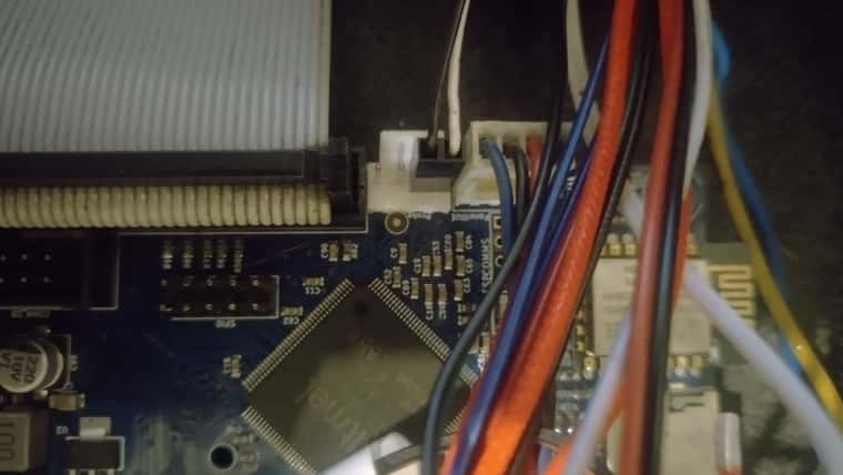
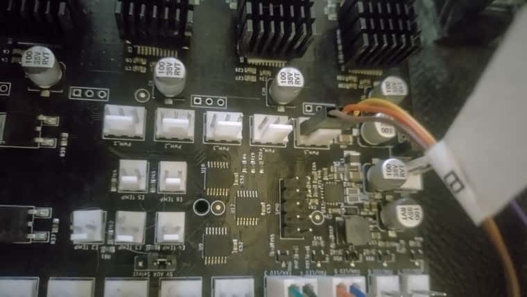
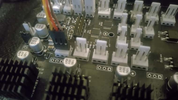
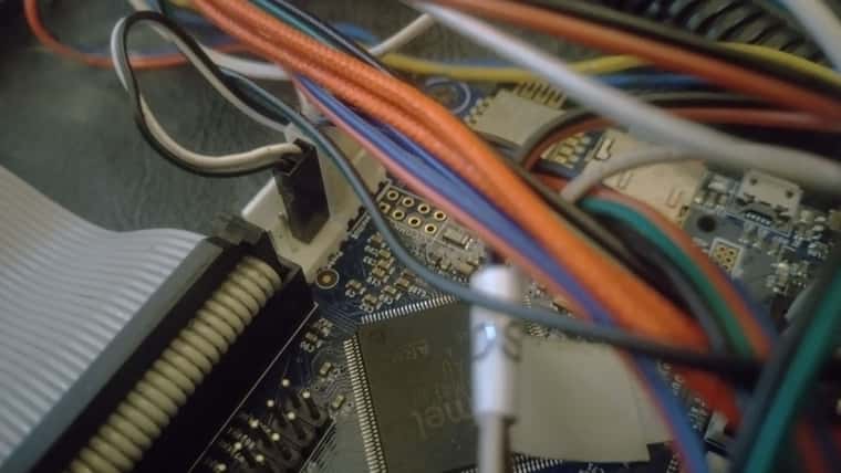
Can you share a photo of the wiring?
-
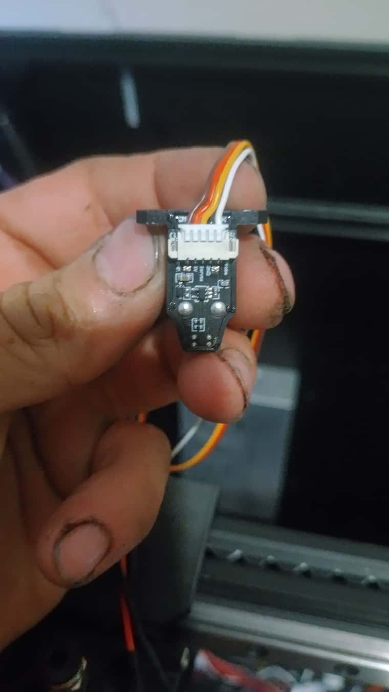
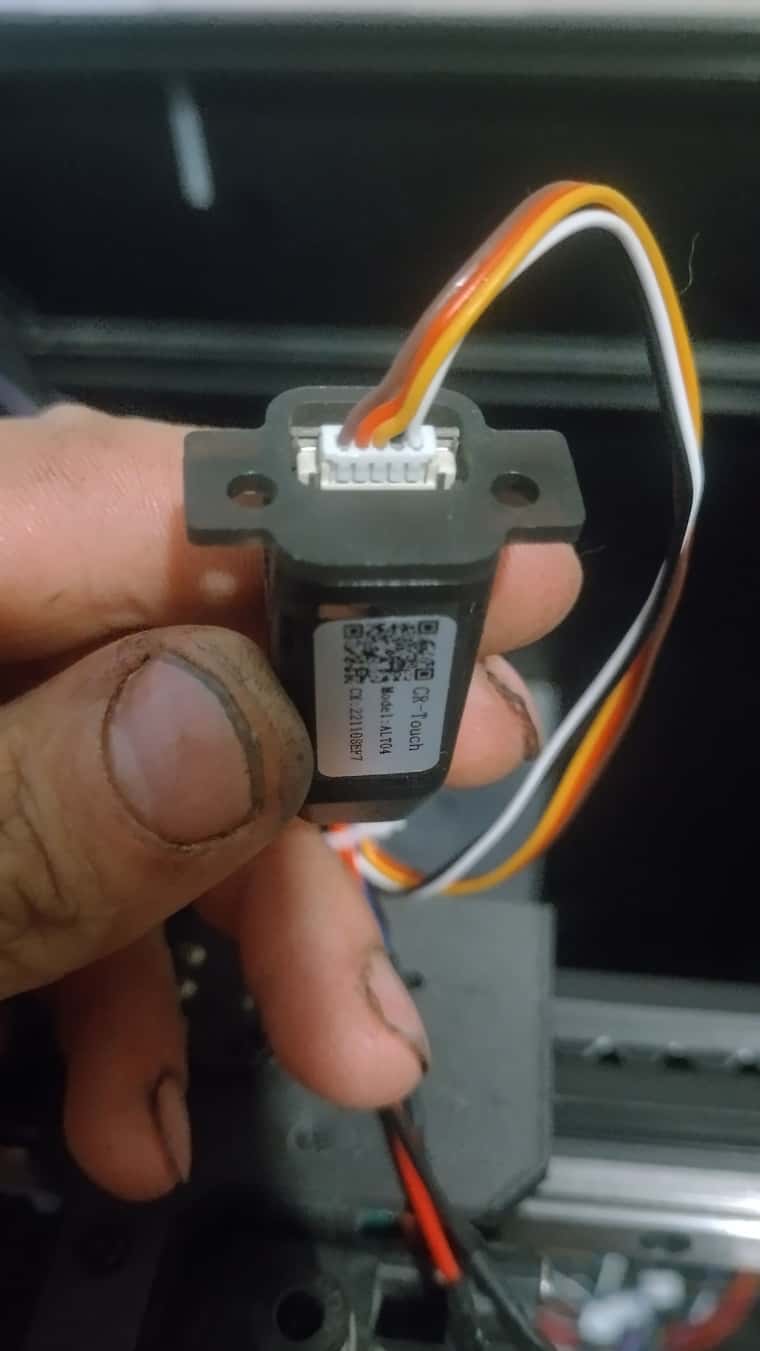
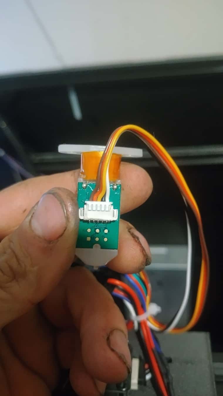
Thank you, here is photos of wiring with the 3 different probes I have (the main one in question is the 3d touch / cr touch)
I'll try removing the ! And see how I get on
Thank you
-
@Craigrobbo Removing the ! worked thank you
-
 undefined Phaedrux marked this topic as a question
-
undefined Phaedrux has marked this topic as solved