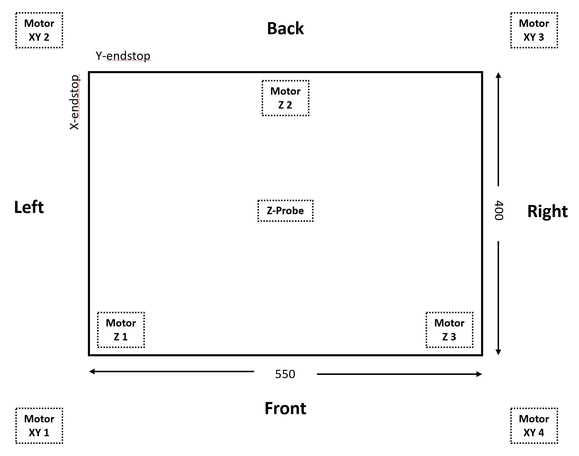
CoreXY with four motors (AWD)
-
I just found that the Y axis on my new coreXY is inverted when I was doing my first heightmap measurement (which wasnt all to straight at all).
Looking at the printer from the top, my endstops are at the back left side instead of the front left side as expected per default of RRF.

I have tried all possible configurations of drivers going backwards or forward and endstop being at the min or max end but there is only one configuration that works with all the motor operating in tandem and not against each other but in that configuration the Y axis is flipped relative to the RRF coordinate system.
Wiring (for cable length reasons):
Motor XY 1 goes to Duet2Wifi E0-Stepper
Motor XY 2 goes to Duet2Wifi Y-Stepper
Motor XY 3 goes to Duet2Wifi E1-Stepper
Motor XY 4 goes to Duet2Wifi X-StepperPlease find my configuration below, do I really have to swap motors on the controller board in order to get orientation right as I understand from some posts?
; Axes
M584 X0.1:0.3 Y0.0:0.4 Z0.5:0.6:0.7 ; set axis mapping
M350 X16 Y16 Z16 I1 ; configure microstepping with interpolation
M906 X2200:2200 Y2200:2200 Z800 ; set axis driver currents
M92 X80 Y80 Z1600 ; configure steps per mm
M208 X0:550 Y0:400 Z0:400 ; set minimum and maximum axis limits
M566 X5000 Y2000 Z100 ; set maximum instantaneous speed changes (mm/min)
M203 X10000 Y80000 Z1500 ; set maximum speeds (mm/min)
M201 X10000 Y6000 Z100 ; set accelerations (mm/s^2); Extruders
M584 E0.2 ; set extruder mapping
M350 E16 I1 ; configure microstepping with interpolation
M906 E1000 ; set extruder driver currents
M92 E420 ; configure steps per mm
M566 E120 ; set maximum instantaneous speed changes (mm/min)
M203 E3600 ; set maximum speeds (mm/min)
M201 E250 ; set accelerations (mm/s^2); Kinematics
M669 K1 ; configure CoreXY kinematics; Endstops
M574 X1 P"xstop" S1 ; configure X axis endstop
M574 Y1 P"ystop" S1 ; configure Y axis endstop; Probes
M558 K0 P1 C"zprobe.in" H5 F120 T6000 ; configure analog probe via slot #0
G31 P200 X0 Y-20 Z0.5 ; set Z probe trigger value, offset and trigger height
M574 Z1 S2 ; Set Z endstop probe
M671 X-38:275:588 Y365:-100:365 S10 ; Z pivot points are at (-15,220), (100,-20) and (215,220); Mesh Bed Compensation
M557 X25:525 Y25:375 S80:80 ; define grid for mesh bed compensation -
@stellator please follow https://docs.duet3d.com/en/User_manual/Machine_configuration/Configuration_coreXY#testing-motor-movement to get the axis directions correct.
-
@stellator I'd put the M669 kinematic declaration before the drive mapping.
-
@o_lampe Thats a good idea! I will try and report..
-
Okay, putting the kinematics definition M669 k1 in front of the driver definition helped in that sense that I can now use 4 out of 8 different direction settings for the four motors (which is in line with my expectation because two motors need to be paired always) instead of only one as was the case before (every other combination resulted in stalling motors).
However, following: https://docs.duet3d.com/en/User_manual/Machine_configuration/Configuration_coreXY#testing-motor-movement again, I can either swap the directions/polarities of both X and Y axis at the same time or I can swap X for Y but I cannot keep X and Y correct and only change the Y polarity as needed, for my Y endstop is at the high end and the tested heightmap (and hence the future print) is mirrored in Y.
Also, its strange that changing the endstop config from high to low does not affect the direction of the homing move as I would expect (but thats maybe due to the formula I copied from the RepRap configurator:
var xTravel = move.axes[0].max - move.axes[0].min + 5 ; calculate how far X can travel plus 5mm
var yTravel = move.axes[1].max - move.axes[1].min + 5 ; calculate how far Y can travel plus 5mmI also did put the motors at different ports and tried the same thing again but with the same result, as expected.
Out of ideas right now, or is it because of the four wheel drive Iam using (AWD, four motors, Voron or whatever is the correct synonym for it)?
-
@stellator Normally, the 'X' stepper is back right on a CoreXY, and the 'Y' stepper is back left. I think you have these the wrong way around.
I think it should be:
Motor XY - 'Y' motor - 1 goes to Duet2Wifi E0-Stepper (driver 3)
Motor XY - 'Y' motor - 2 goes to Duet2Wifi Y-Stepper (driver 1)
Motor XY 3 - 'X' motor - goes to Duet2Wifi E1-Stepper (driver 4)
Motor XY 4 - 'X' motor - goes to Duet2Wifi X-Stepper (driver 0)So your M584 should be
M584 X0.0:0.4 Y0.1:0.3 Z0.5:0.6:0.7 ; set axis mappingThen check the direction of movement for the motors, using https://docs.duet3d.com/User_manual/Machine_configuration/Configuration_coreXY#testing-motor-movement, reversing the pairs of motors' direction as necessary.
Edit: I don't think it's 4WD problem, so long as the pairs of motors are working in the same direction as each other. Though it may be easier to get it working in 2WD first!
Ian
-
This post is deleted!