• Tags
  • Documentation
  • Order
  • Register
  • Login
Duet3D Logo Duet3D
  • Tags
  • Documentation
  • Order
  • Register
  • Login

[FW 3.5.2] M569.2 and microstepping lookup table

Scheduled Pinned Locked Moved
Tuning and tweaking
4
21
940
Loading More Posts
  • Oldest to Newest
  • Newest to Oldest
  • Most Votes
Reply
  • Reply as topic
Log in to reply
This topic has been deleted. Only users with topic management privileges can see it.
  • undefined
    dc42 administrators @leone
    last edited by 27 Aug 2024, 08:09

    @leone please try the firmware build at https://www.dropbox.com/scl/fo/42aeqn7cndtkwe36nwkig/APkS2re8b3ROZZu0Z2NggxA?rlkey=z704mbv9kd3o6t67i857nhtl1&dl=0 and see if that fixes it.

    Caution: although this build reports itself as 3.5.3-rc.1 the final 3.5.3-rc.1 build we release may be different.

    Duet WiFi hardware designer and firmware engineer
    Please do not ask me for Duet support via PM or email, use the forum
    http://www.escher3d.com, https://miscsolutions.wordpress.com

    1 Reply Last reply Reply Quote 0
    • undefined
      dc42 administrators @leone
      last edited by 29 Aug 2024, 09:23

      @leone this issue is probably fixed in RRF 3.5.3-rc.1 released yesterday.

      Duet WiFi hardware designer and firmware engineer
      Please do not ask me for Duet support via PM or email, use the forum
      http://www.escher3d.com, https://miscsolutions.wordpress.com

      undefined 1 Reply Last reply 3 Sept 2024, 13:23 Reply Quote 0
      • undefined
        leone @dc42
        last edited by 3 Sept 2024, 13:23

        @dc42 thank you for having looked into that, the conversion now works.
        Unfortunately, the behavior of the motors after changing the lookup table is still not the same as with the TMCL-IDE.

        undefined 1 Reply Last reply 5 Sept 2024, 07:18 Reply Quote 0
        • undefined
          dc42 administrators @leone
          last edited by 5 Sept 2024, 07:18

          @leone did you change the hysteresis values to the ones given by the TMC IDE too?

          Duet WiFi hardware designer and firmware engineer
          Please do not ask me for Duet support via PM or email, use the forum
          http://www.escher3d.com, https://miscsolutions.wordpress.com

          undefined 1 Reply Last reply 6 Sept 2024, 13:25 Reply Quote 0
          • undefined
            leone @dc42
            last edited by 6 Sept 2024, 13:25

            @dc42 yes, I set the driver parameters as in the TMCL-IDE (I copied the contend of the register 0x6C with M569.2).
            I am using a custom board, I will check over the next few days if there is interference in the output of the TMC5160 distorting the signal going to the motor.

            1 Reply Last reply Reply Quote 0
            • undefined
              AndyE3D
              last edited by 17 Sept 2024, 11:50

              @leone I am trying to understand what the phase modulation settings in TMCL-IDE are doing exactly but I can't see any reference to it in the user manual.

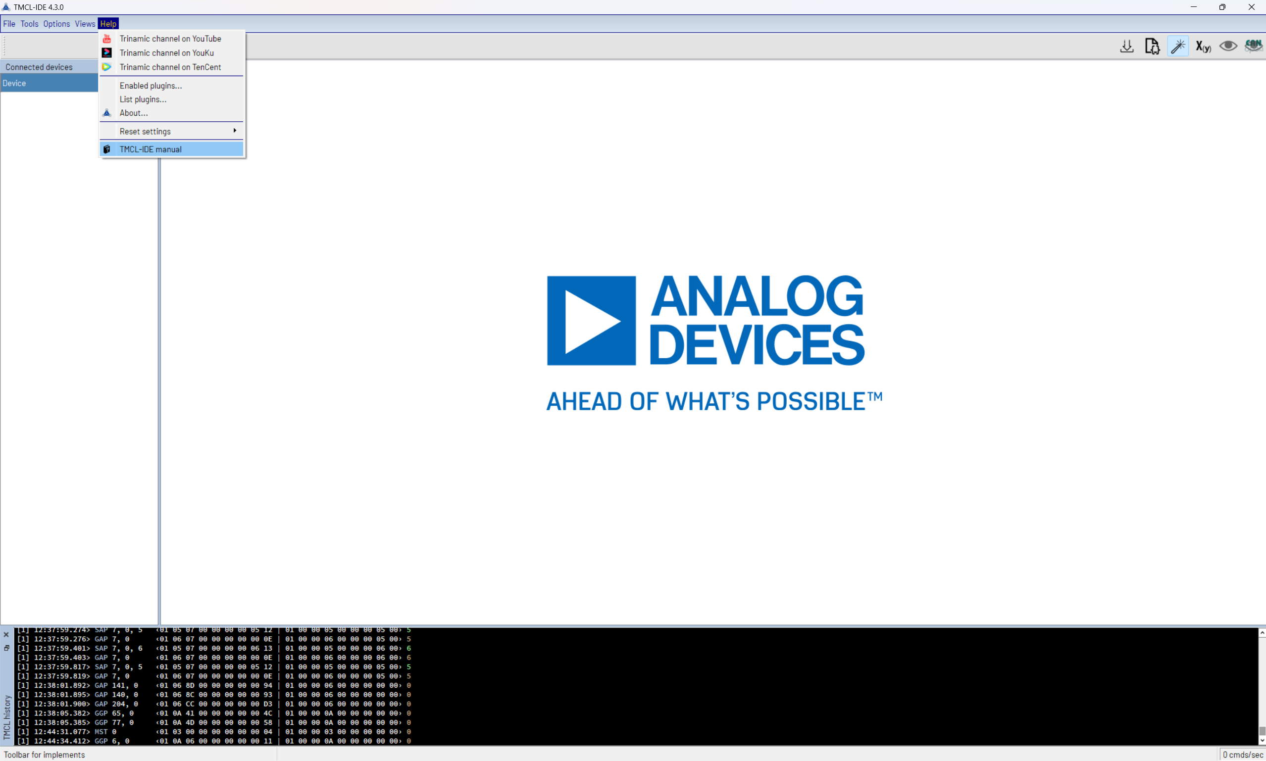
              • What steps did you take to get that window in TMCL-IDE?
              • Are you using a physical dev board (if so which one), or are you simulating the board with a virtual module in the IDE (again which one)?
              undefined 1 Reply Last reply 17 Sept 2024, 12:10 Reply Quote 0
              • undefined
                leone @AndyE3D
                last edited by 17 Sept 2024, 12:10

                @AndyE3D I am using the TMC5160 evaluation kit (https://www.mouser.de/ProductDetail/ADI-Trinamic/TMC5160-EVAL-KIT?qs=TiOZkKH1s2TJebvRqsmGsQ%3D%3D).
                Once you connect the eval-kit to the pc you will find something called "sinus tool" and you can play with it. This is what in the user manual is called "microstepping look-up table"... I'm not sure if with "phase modulation" you're referring to the same thing.

                undefined 1 Reply Last reply 17 Sept 2024, 13:30 Reply Quote 0
                • undefined
                  AndyE3D @leone
                  last edited by 17 Sept 2024, 13:30

                  @leone Can you share the user manual you are using as "microstepping look-up table" also isn't in the one I have from the software
                  c4b6a487-49a8-4867-b1b1-182b26483871-image.png.

                  I also don't have an evaluation board so I might need you to try and change the sliders and share with me what each one does if you are happy to help me with that?
                  abb73207-b8ff-45eb-8ff5-2cdf9cf37a15-image.png

                  undefined 1 Reply Last reply 17 Sept 2024, 13:53 Reply Quote 0
                  • undefined
                    leone @AndyE3D
                    last edited by 17 Sept 2024, 13:53

                    @AndyE3D I followed the driver's datasheet and the application note 26:
                    https://www.analog.com/en/resources/app-notes/an-026.html
                    https://www.analog.com/media/en/technical-documentation/data-sheets/TMC5160A_datasheet_rev1.17.pdf
                    These are settings strongly dependent on the motor itself, and I have only nema24 motors. The configuration I posted is the best I found for this type of motor.

                    undefined 1 Reply Last reply 18 Sept 2024, 11:32 Reply Quote 0
                    • undefined
                      dc42 administrators @leone
                      last edited by dc42 18 Sept 2024, 11:32

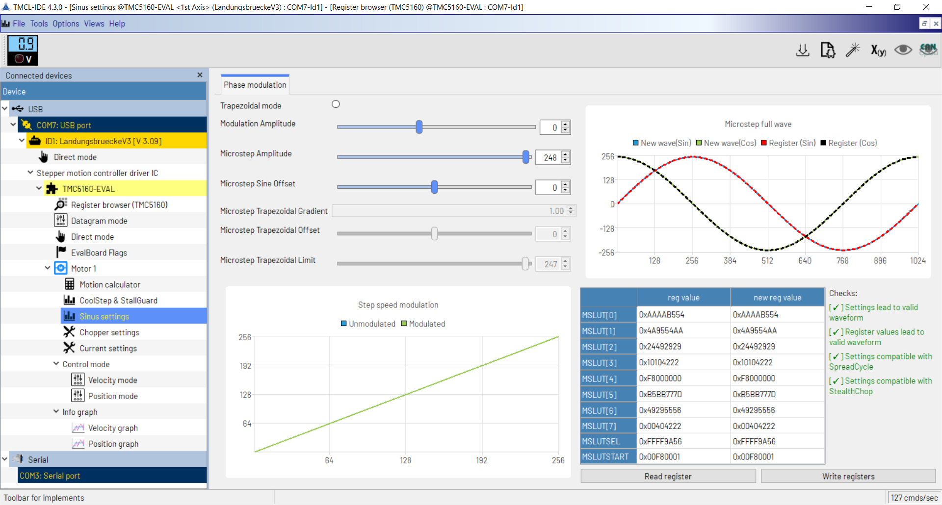
                      Hi @leone, if it's not too much trouble, please can you load the IDE and post screenshots similar to the ones you posted already (showing the sliders, waveform, and register values) with the sliders set in the following positions:

                      1. Modulation amplitude zero, sine offset zero.
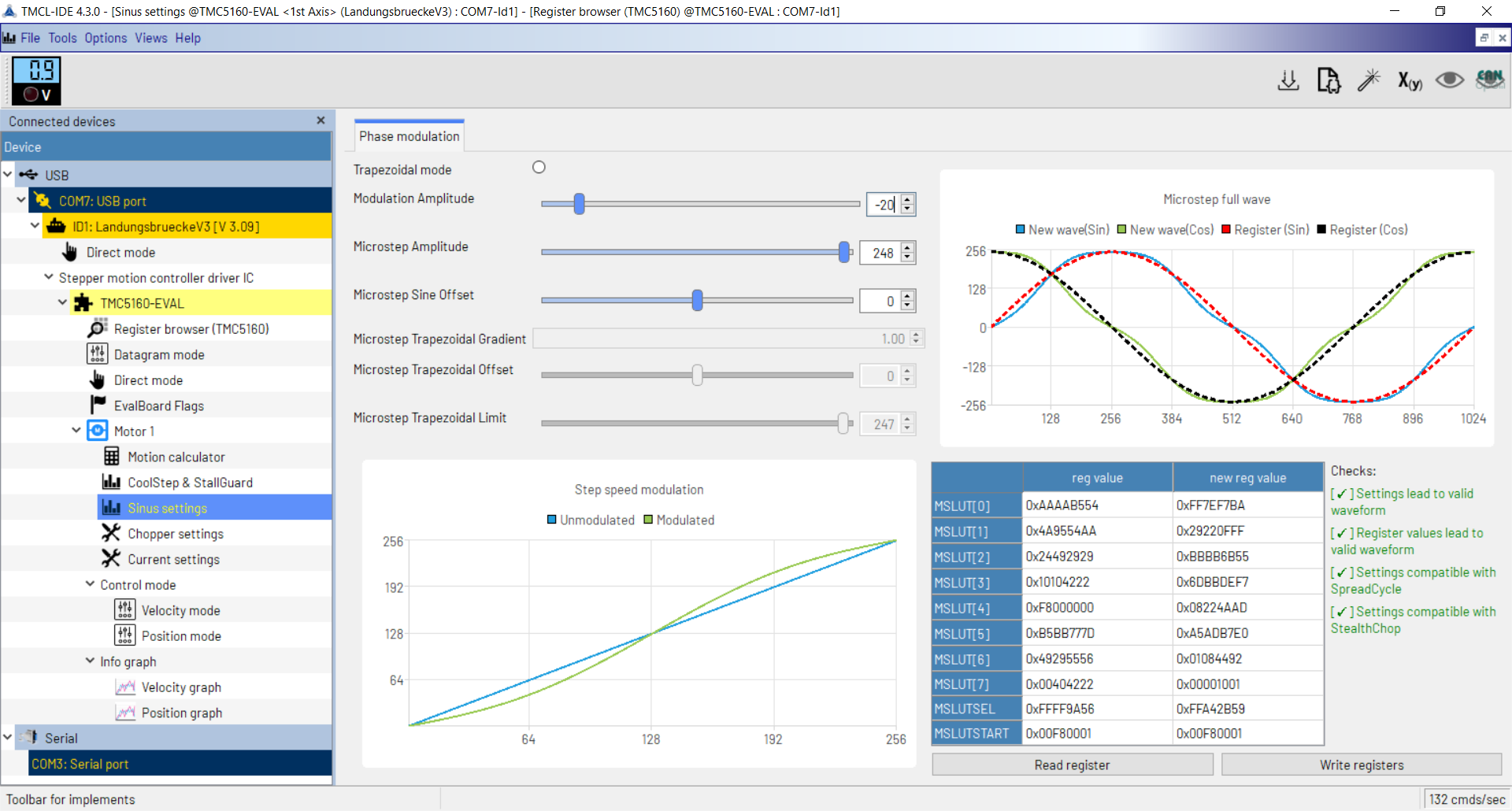
                      2. Modulation amplitude -20, sine offset zero,
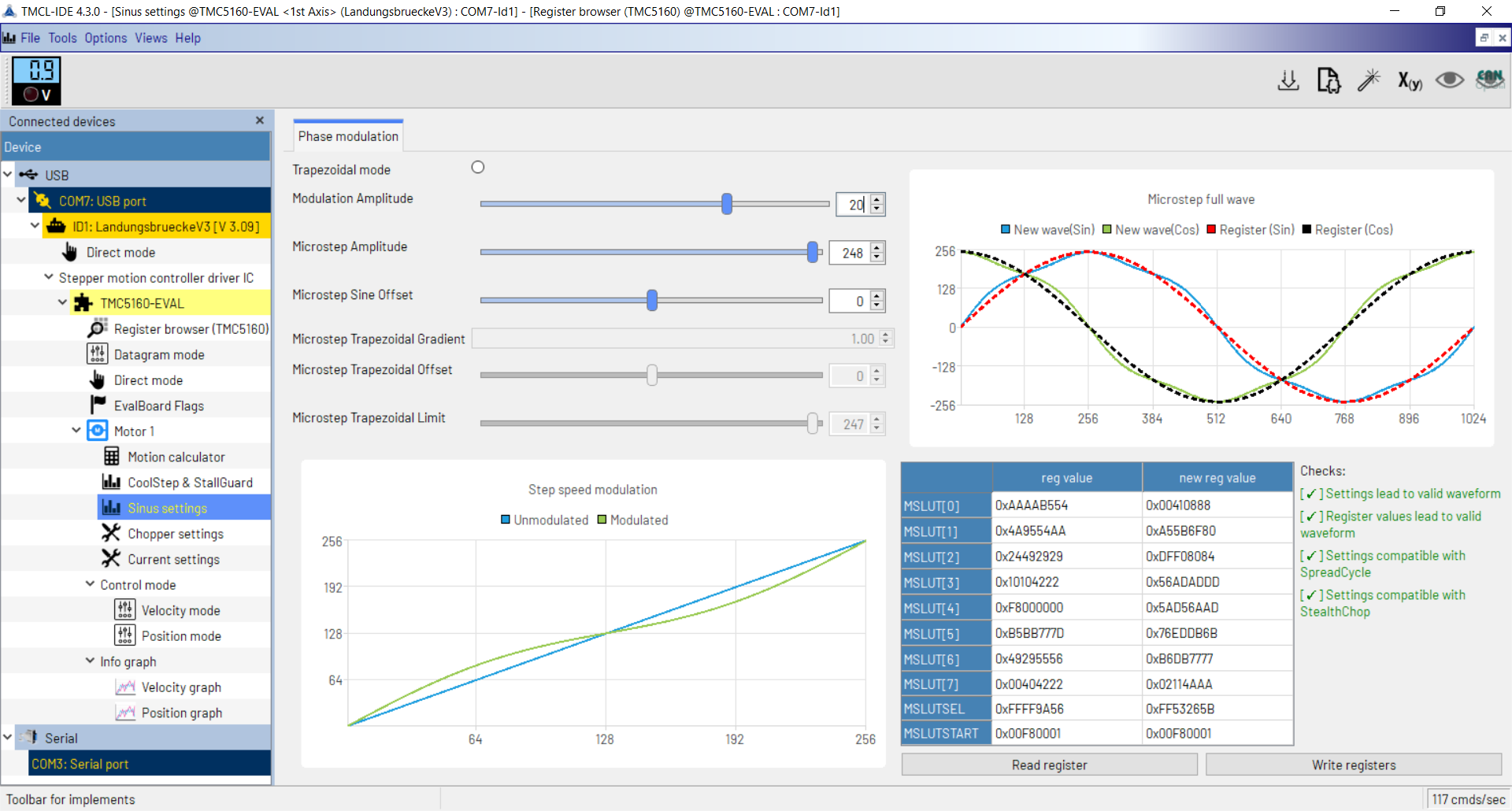
                      3. Modulation amplitude +20, sine offset zero.
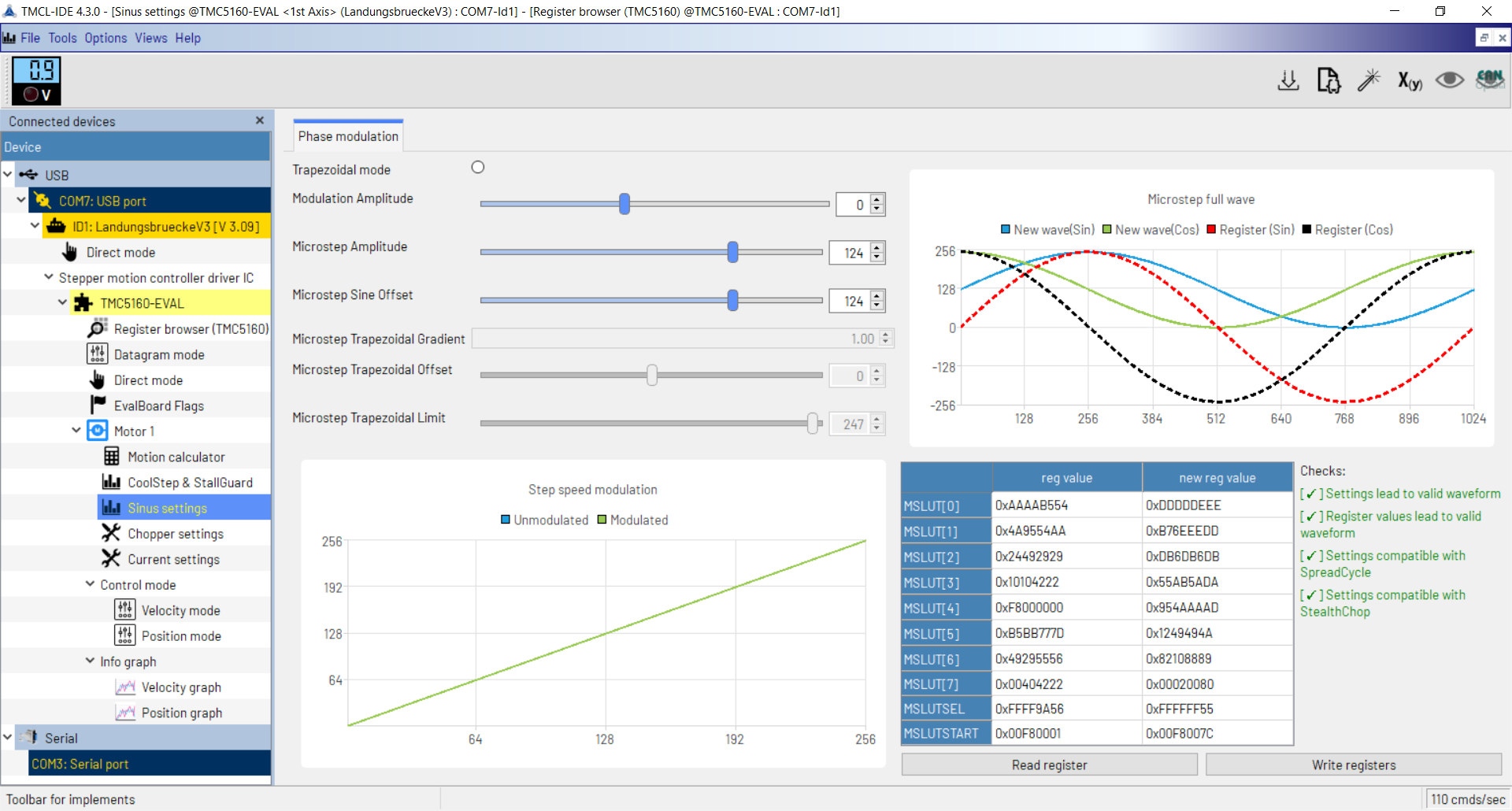
                      4. Modulation amplitude zero, sine offset maximum.

                      You may need to adjust the microstep amplitude in some cases to make the checks pass.

                      My aim is to see whether the "modulation" is just adding some third harmonic to the sine wave, or something more complicated; and to see what the sine offset does.

                      Thanks - David

                      Duet WiFi hardware designer and firmware engineer
                      Please do not ask me for Duet support via PM or email, use the forum
                      http://www.escher3d.com, https://miscsolutions.wordpress.com

                      undefined 1 Reply Last reply 18 Sept 2024, 14:34 Reply Quote 0
                      • undefined
                        leone @dc42
                        last edited by 18 Sept 2024, 14:34

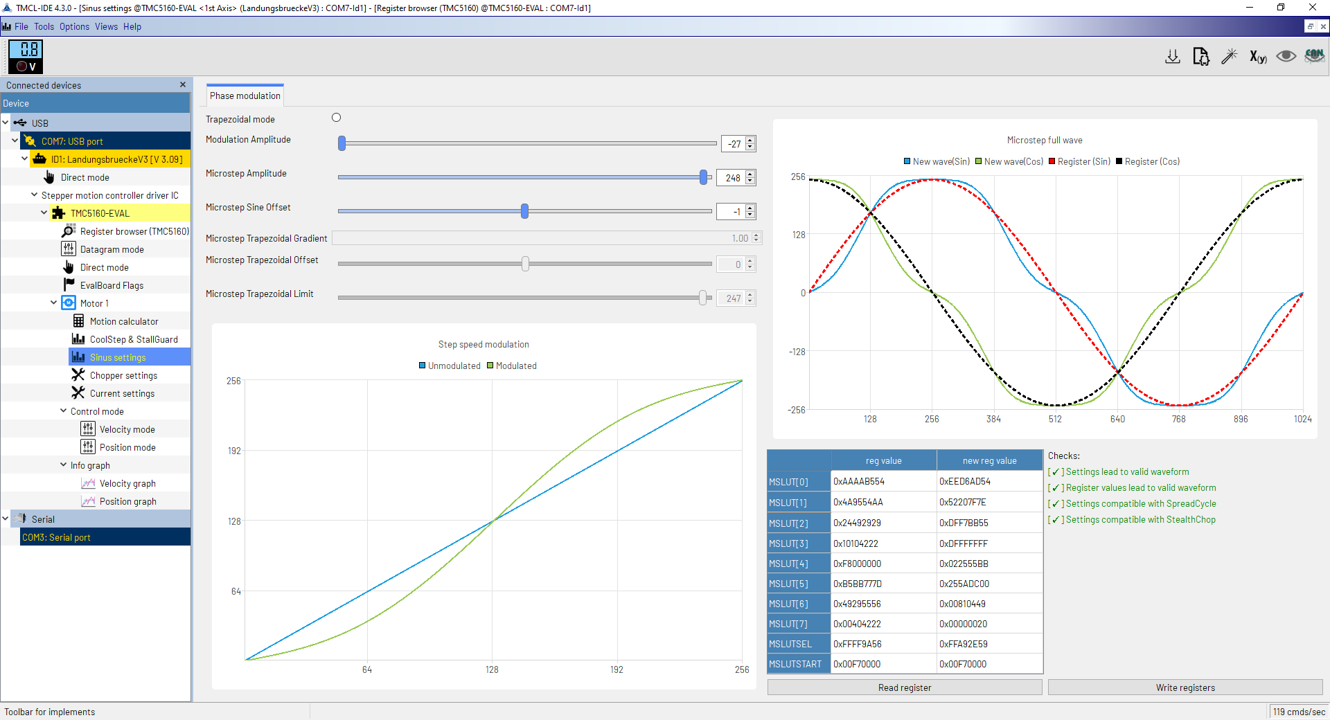
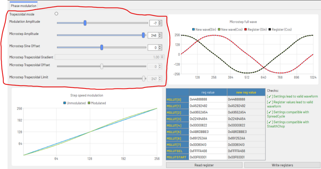
                        @dc42 here they are. The sine offset should be "the absolute current at entry of the lookup table". It shifts up or down the sine wave, so to have it feasible I had to reduce the microstep amplitude. The maximum offset is not feasible, the higher it gets, the flatter the sinewave must be. Hope it's enough to clarify the behaviour, if you need something else, let me know.

                        mod0_off0.PNG
                        modm20_off0.PNG
                        modp20_off0.PNG
                        mod0_off124.PNG

                        undefined 1 Reply Last reply 18 Sept 2024, 16:48 Reply Quote 0
                        • undefined
                          dc42 administrators @leone
                          last edited by 18 Sept 2024, 16:48

                          @leone thanks, that's great!

                          The sine offset isn't what I expected, and I don't see any use for it. Does the IDE documentation or help indicate when it would be useful?

                          Duet WiFi hardware designer and firmware engineer
                          Please do not ask me for Duet support via PM or email, use the forum
                          http://www.escher3d.com, https://miscsolutions.wordpress.com

                          undefined 1 Reply Last reply 19 Sept 2024, 12:57 Reply Quote 0
                          • undefined
                            leone @dc42
                            last edited by 19 Sept 2024, 12:57

                            @dc42 unfortunately, the IDE doesn't say anything more than the datasheet/application notes.
                            My understanding here is that the sine wave is encoded as a list of increments/decrements to add to the START_SIN and START_SIN90 registries while increasing the microsteps. Since START_SIN and START_SIN90 represent the current of the two coils at the beginning of the electrical revolution, the value has to be greater or equal than zero.
                            It can be tuned for some desired behaviours or to make some weird configurations feasible (as in the picture below, where for offset less than 28 the wave is not feasible).
                            In general, from the examples in the datasheet and application notes, I saw the START_SIN registry always set to zero.

                            Capture.PNG

                            undefined 1 Reply Last reply 19 Sept 2024, 16:51 Reply Quote 0
                            • undefined
                              dc42 administrators @leone
                              last edited by 19 Sept 2024, 16:51

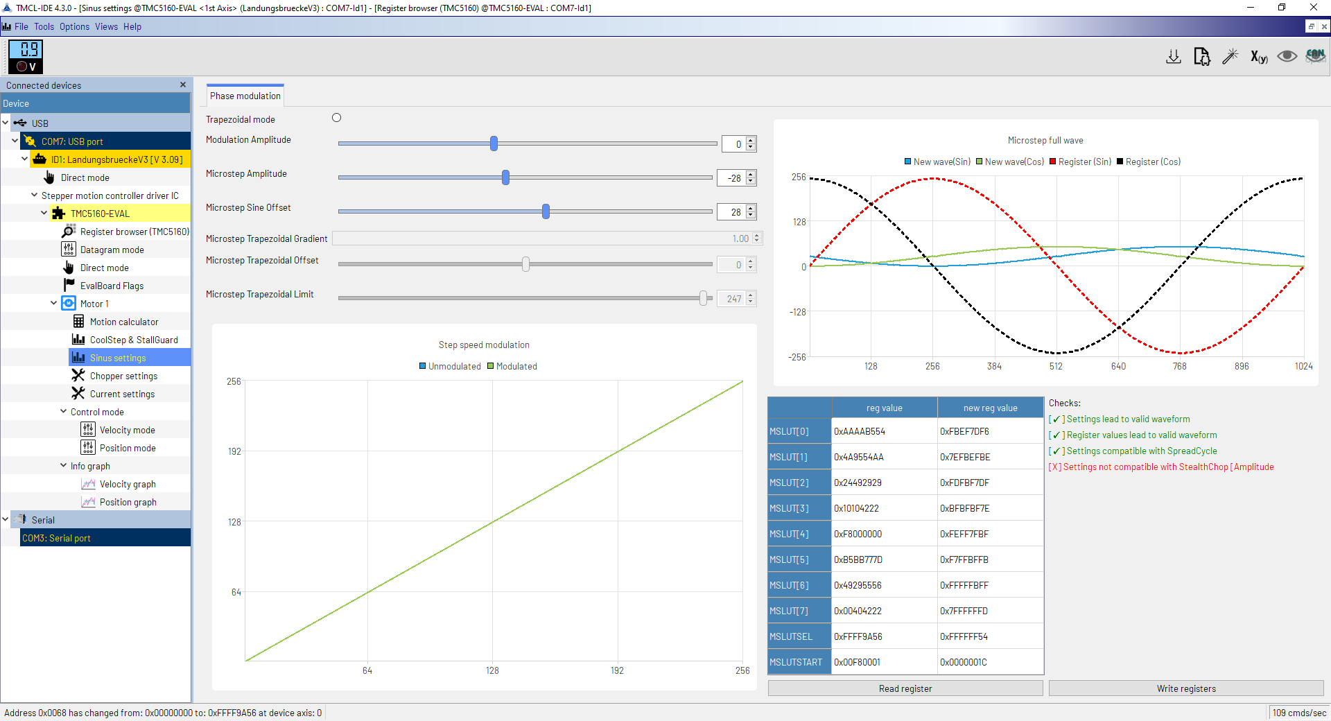
                              @leone thanks again!

                              We're looking to add the facility to apply "modulation" to the sine table using just 1 or 2 parameters. What are the max and min values of "modulation" that the IDE allows you to apply? Please provide screenshots using those values.

                              Duet WiFi hardware designer and firmware engineer
                              Please do not ask me for Duet support via PM or email, use the forum
                              http://www.escher3d.com, https://miscsolutions.wordpress.com

                              undefined 1 Reply Last reply 20 Sept 2024, 08:14 Reply Quote 0
                              • undefined
                                leone @dc42
                                last edited by 20 Sept 2024, 08:14

                                @dc42 great news!
                                The modulation parameter goes from -27 to 39.

                                maxMod.PNG minMod.PNG

                                1 Reply Last reply Reply Quote 0
                                • First post
                                  Last post
                                Unless otherwise noted, all forum content is licensed under CC-BY-SA