Configuring Spindle Outputs
-
Hi,
How can I enable the spindle in WebControl while simultaneously turning on e0heat and e1heat? e0heat is used to turn the spindle on/off, and e1heat serves as a PWM output to control the spindle speed.

Thank you very much for your support!
-
@an-andrew How have you defined the spindle currently? You need to define it with M950, see https://docs.duet3d.com/en/User_manual/Reference/Gcodes#m950-create-heater-fan-spindle-led-strip-or-gpioservo-pin
Specifically:(RRF 3.3 and later) When using M950 to create a spindle use the following format:
M950 R0 C"pwm_pin + on/off_pin + forward/reverse_pin" Qfff Laa:bbC can have 1, 2 or 3 pins.
The first pin defines a pwm-capable pin to set the spindle speed.
If a second pin is defined it is used as spindle on/off.
If a third pin is defined it is used as spindle forward/reverse.
"fff" is the PWM frequency as usual
"Laa:bb" sets the RPM range as "aa" to "bb". "Lbb" just sets the max RPM to "bb". Default RPM values are 60 min 10000 maxSo you define:
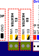
M950 R0 C"e1heat+e0heat" Q2000 ; adjust PWM frequency to match your VFDNote that the e1heat and e0heat pins switch to GND; they do not provide a voltage as a signal. This may or may not be correct for your VFD; most likely it is not correct. If it expects a 3.3V signal, you can use the pins on the expansion header, eg exp.heater3 and exp.heater5. If your VFD needs a 10V signal, you will need to use PWM to voltage board, see https://docs.duet3d.com/en/User_manual/Machine_configuration/Configuration_CNC#connecting-a-spindle
If you continue to have problems, post the make and model of your VFD.
Ian
-
Ian, thank you very much for your support. However, I have already managed to adjust the code myself. What surprises me is the statement that e1heat switches to GND. When I measure it, I get the voltage that is supplied to the board. I have a Duet 2 WiFi board.
Best regards.
-
@an-andrew If you look at the pin out of any of the heater outputs on the board, you'll see the pins are labelled +VIN (Voltage IN, or the supply voltage, usually 12-24V) and E#-. The E#- is the e#heat pin, and switches VIN to GND. This is because MOSFETs need to come after the load (ie the heater) in the circuit, so the e#heat pins are PWM-to-GND pins. They do not supply a signal in the form of a voltage. The fan outputs are the same. It will depend on your VFD if you can use this signal. Which VFD do you have?
Ian
-
Okay, I think I understand. I am using a Huanyang 2.2kW 230V VFD. It outputs a voltage, so I would only need a normally closed switch. I would then connect E#- to GND, correct?
Although, thinking about it again, that's not right. I would need a relay, that should definitely work.
-
@an-andrew said in Configuring Spindle Outputs:
I am using a Huanyang 2.2kW 230V VFD. It outputs a voltage, so I would only need a normally closed switch.
I don't quite understand what you're saying here. If you've got something like the Huanyang HY series VFDs, the most common method to control them is supplying a 0-10V signal, which the VFD has an input for. A PWM signal (either positive or to-GND) doesn't work. Usually you need to use a PWM to analogue converter to do this; see https://docs.duet3d.com/en/User_manual/Machine_configuration/Configuration_CNC#connecting-a-spindle
I would then connect E#- to GND, correct?
No.
Although, thinking about it again, that's not right. I would need a relay, that should definitely work.
No, you need a PWM to analogue converter, that takes the PWM signal and converts it to 0-10V. See the link above.
Your only other alternative is to replace your Duet 2 with a Duet 3, which has support for RS485/Modbus communication in the latest firmware, which I think most Huanyang VFDs support.Ian
-
Thanks for your support. I wasn’t clear earlier. I'm now using E1 to turn the spindle on and off, with a relay in between. Of course, I'm using a PWM to Analog 1-10V converter for speed control, and that runs through E0. It's working now.
Do you have any idea why the spindle speed fluctuates slightly, even though I haven’t changed any settings? I'm currently using the blue PWM to 1-10V converter. I've already ordered a better one that might solve the issue.
-
@an-andrew I had that when I had one of those VFDs. I never got to the bottom of it.
I would suggest not looking into it too much as RS485 control is part of 3.6 beta 1 and that gives much better control -
@an-andrew said in Configuring Spindle Outputs:
Thanks for your support. I wasn’t clear earlier. I'm now using E1 to turn the spindle on and off, with a relay in between. Of course, I'm using a PWM to Analog 1-10V converter for speed control, and that runs through E0. It's working now.
Ah, sorry, I thought you were talking about the spindle speed control, rather than spindle on/off. But it sounds like you sorted it out, despite what I said!
Do you have any idea why the spindle speed fluctuates slightly, even though I haven’t changed any settings? I'm currently using the blue PWM to 1-10V converter. I've already ordered a better one that might solve the issue.
As @jay_s_uk says, it's a 'feature' of the PWM to analogue conversion boards! And as he says, RS485 control is coming, though unfortunately for you not to Duet 2, which is on the very limit of available memory (512kb).
Ian
-
This is my project.
https://youtu.be/Y9D3ahjihwk?si=2dGHNQtp5sv1Uhh9 -
@an-andrew that's an awesome machine
-
Hello everyone,
I have a water-cooled spindle and would like to implement the following scenario:
When I turn on my spindle with the M5 command, my coolant pump (24V) should automatically start to cool the spindle. In addition to controlling the spindle speed and turning it on and off, I want to turn on a pump as well.
It is important that the coolant pump continues running for about one minute after the spindle is turned off (M5), before it completely shuts down. Is there a way to implement this with some logic or an output signal?
M950 R0 C"e0heat+e1heat" Q1000 L24000           ; Configure spindle on e0heat + e1heat, PWM at 1000 Hz


; Tools and Spindle
M563 P0 R0 S"Spindle"                           ; Define Tool 0 as spindle
G10 P0 X0 Y0 Z0                                 ; Set tool 0 axis offsets
M568 P0 F6000                                      ; Set tool 0 default RPM
Thank you in advance for your support!