Modbus Spindle Control
-
@NineMile said in Modbus Spindle Control:
f you discount CRC, the only real difference between the Modbus gcodes and the UART gcodes is that the Modbus ones restrict the functions that can be called. It might make more sense to add a CRC option to the UART commands and let the caller build the packet contents in whatever fashion they want rather than having commands specifically for modbus-rtu.
I don't think that is really the case. If you take a look at the modbus write funtion here: https://github.com/Duet3D/RepRapFirmware/blob/3.6-dev/src/Comms/AuxDevice.cpp#L190
You will see there are extra calls around the actual write operations. My understanding is that these work with the low level UART code (in coreN2G) to ensure that the modbus data is written as a single "burst" of bytes (avoiding possible issues with task switches between writing bytes) and that there is a sufficiently long period of "no data" between packets (in effect modbus uses no data as a packet delimiter). None of that is present in the standard UART write code (this is what my comments about "timing" referred to above). Oh and there is also the handling of the RS485 transceiver read/write pin which is needed if that does not do auto switching. So at the very least we would need to identify if the UART is in "modbus" mode or not. There is then also the handling of "read" operations which are really a write followed by a read, again I think that this has timing considerations that don't really apply to the normal UART read.
So I think there might still be a case for having modbus specific read/write operations but I'd be tempted to try and make them more generic ones that simply read/write a bunch of bytes and apply the timing and crc to them, but leave the formatting and decoding of those bytes up to the user in the form of a script?
That's my take on this, I'd be interested to hear @dc42 take on the matter. To help with that, do you have any feel for how often spindle commands are actually issued and what sort of polling might be needed for status reporting? Can this status polling perhaps be optimised by for instance only doing some of it immediately after issuing a command?
-
@gloomyandy said in Modbus Spindle Control:
I don't think that is really the case. If you take a look at the modbus write funtion here: https://github.com/Duet3D/RepRapFirmware/blob/3.6-dev/src/Comms/AuxDevice.cpp#L190
Ah yep, good point on the timing concerns. So the user on Discord who has used the UART functions to implement the HY style "Modbus" comms might just be getting lucky with timing / silent durations that work for that particular VFD but with no guarantee of working on others.
@gloomyandy said in Modbus Spindle Control:
So I think there might still be a case for having modbus specific read/write operations but I'd be tempted to try and make them more generic ones that simply read/write a bunch of bytes and apply the timing and crc to them, but leave the formatting and decoding of those bytes up to the user in the form of a script?
I think there's definitely scope for this. I wanted to use the
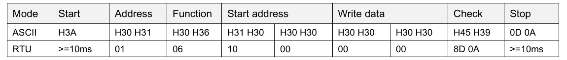
0x08Modbus function before to autoscan for devices on the bus, but this is not currently possible using the Modbus read / write functions as that function code is not implemented.Reducing these functions to taking a station address and a data field (everything between address and check fields in the below image) would work well (ignore ASCII mode I wanted to include the headers).
@gloomyandy said in Modbus Spindle Control:
That's my take on this, I'd be interested to hear @dc42 take on the matter. To help with that, do you have any feel for how often spindle commands are actually issued and what sort of polling might be needed for status reporting? Can this status polling perhaps be optimised by for instance only doing some of it immediately after issuing a command?
I would say under normal circumstances, control commands would be executed on a similar cadence to tool changes. For each machining operation in a gcode file, you would usually stop the spindle, run a tool change, set the spindle RPM and then start the spindle.
In my particular use case, I also want to be able to monitor the output speed of the VFD on a regular basis so I can pause or abort the job if the VFD triggers an error - it would be quite important to do that quickly, but I think polling the VFD every half a second or so is enough.
From a control perspective, the worst case scenario I can think of right now is my implementation of variable spindle speed control - it actively changes the rpm of the spindle up and down constantly to avoid resonance frequencies, and right now that happens at the same rate as polling the VFD (every 500ms).
From a start / stop perspective, I think the worst case might be something like the rapidchange toolchanger, which starts and stops the spindle in both directions within a couple of seconds.
So I think at the absolute worst case we're looking at half a second between spindle control commands or status checks.
Edit: I don't think status checks can be optimised to only check after commands. Imagine if you start a spindle and then run a 10 min machining op, and 8 mins in the VFD overheats and shuts down. RRF wouldn't know about that and could potentially keep running the toolpath while the spindle is stopped, which would cause all sorts of issues including potential broken tools. I do think the status checking needs to be running at all times while a spindle is running.
-
@NineMile said in Modbus Spindle Control:
Edit: I don't think status checks can be optimised to only check after commands. Imagine if you start a spindle and then run a 10 min machining op, and 8 mins in the VFD overheats and shuts down. RRF wouldn't know about that and could potentially keep running the toolpath while the spindle is stopped, which would cause all sorts of issues including potential broken tools. I do think the status checking needs to be running at all times while a spindle is running.
As I said above I'm not a big fan of using modbus for serious errors, personally I'd say you should be using some sort of trigger from a hardware fault signal for that. But even in this case I suspect that the reality is that a second (or possibly) more would be fast enough to handle that situation.
My thoughts on checking for a response after a command was that perhaps you can use a slower polling rate during "normal operations" and only increase that rate if you need to after say issuing a command. But really that is just detail and probably depends a lot on the actual use case.
I'm curious in the table above, it lists a "start" value, but I don't see any mention of that either in the spec I linked to or the code. Where is that table from?
-
@gloomyandy said in Modbus Spindle Control:
As I said above I'm not a big fan of using modbus for serious errors, personally I'd say you should be using some sort of trigger from a hardware fault signal for that. But even in this case I suspect that the reality is that a second (or possibly) more would be fast enough to handle that situation.
I agree with this to a point, but I'd take a guess that at the moment, the majority of spindles that are being run from RRF will be running without any feedback from the VFD at all - because just getting them connected up and running with direction control is complex enough, let alone working out how to get feedback inputs and writing RRF macros to process them properly.
The best thing about Modbus control is only needing to run 2 wires to the VFD, and getting 2-way communication with minimum complexity on the hardware side.
IMO It's much easier to write spindle control macros for a particular VFD type once that include some level of machine and vfd protection using Modbus feedback than it is to walk people through the hardware and VFD setup to implement hardware-based alarming and failure recovery. Especially with all the different types of VFDs out there that all seem to work slightly differently on the hardware side as well.
@gloomyandy said in Modbus Spindle Control:
I'm curious in the table above, it lists a "start" value, but I don't see any mention of that either in the spec I linked to or the code. Where is that table from?
I mentioned this briefly in the gcode I posted for the other style of control - this is from the VFD manual for the Shihlin SL3 which regardless of modbus-rtu spec, specifies a quiet time of 10ms between requests to give the VFD processor enough time to respond. If you send a request before this 10ms timer is up the request errors out.
Attaching the SL3 manual here because I think it's probably one of the most verbose VFD manuals I've come across that explains the Modbus control approach.
-
@gloomyandy said in Modbus Spindle Control:
So I think there might still be a case for having modbus specific read/write operations but I'd be tempted to try and make them more generic ones that simply read/write a bunch of bytes and apply the timing and crc to them, but leave the formatting and decoding of those bytes up to the user in the form of a script?
Looking at the Modbus gcodes again this evening (
M260.1andM261.1) and it occurs to me that if the user has the ability to send arbitrary data then there's no distinction between these 2 commands.It seems like this lower-level "raw" behaviour could be achieved with a single gcode that takes raw bytes and expects a particular number of bytes in response, something like this:
; Purely hypothetical request that expects 3 data bytes returned from the 3 byte data request.
; var.modbusRaw would be a vector of bytes
M261.3 B3 D{10,12,14} V"modbusRaw"
The underlying implementation would send the station address and deal with CRC, but everything to do with the data would be up to the user.
-
@NineMile the Modbus protocol specifies what response is expected to each command. RRF checks those responses. We could ads a generic command but as the response to such a command would be undefined, we would not be able to check it.
Appending the CRC would only be appropriate if the non-Modbus device used the same CRC rules as Modbus.
Duet WiFi hardware designer and firmware engineer
Please do not ask me for Duet support via PM or email, use the forum
http://www.escher3d.com, https://miscsolutions.wordpress.com -
@dc42 I had a quick look at the linuxCNC HAL code for the VFD that the user over on discord was using. That looks like it uses the same crc16 and seed as modbus but has a different payload. I get the impression from a quick scan of the linuxCNC stuff that this is fairly common, devices which claim to be "modbus" use the modbus signal timing. framing and crc but do not use the modbus register/coil model and associated commands. But I'm certainly no expert on this.
-
@gloomyandy said in Modbus Spindle Control:
@dc42 I had a quick look at the linuxCNC HAL code for the VFD that the user over on discord was using. That looks like it uses the same crc16 and seed as modbus but has a different payload. I get the impression from a quick scan of the linuxCNC stuff that this is fairly common, devices which claim to be "modbus" use the modbus signal timing. framing and crc but do not use the modbus register/coil model and associated commands. But I'm certainly no expert on this.
This is my understanding as well. Theres at least a couple quite common Chinese VFD's which advertise Modbus support but don't follow the modbus-rtu data format - the Huanyang one encountered on Discord seems to be the most common though.
For my own understanding of the RRF codebase, I spent a bit of time looking at how custom spindle control might be implemented using
DoFileMacro.It seems like adjusting spindle state and rpm would probably need to move to some type of reconciliation based system - where direct calls to
spindle->SetRpm()andspindle->SetState()would store values that would then be applied later while spinning aGCodeBuffer.Applying the settings could be simply setting pin output states for a standard spindle config, like what happens now, or calling
DoFileMacroto execute a user-provided control system.However - there's areas in the code where spindle control actions appear to be taken from outside any particular
GCodeBuffer(Tool::Activate()for example, called from direct LCD requests). These would not map cleanly onto just switching into a spindle control state in the currentGCodeBufferwhere the request was made.My initial thought was to use the Daemon buffer for all spindle control, but a long-running daemon macro could impact spindle control, and vice-versa.
Does it make sense to run the spindle control actions in their own
GCodeBufferinstance and synchronise it with the other buffers?For example - when
Filebuffer callsM3to start the spindle, we change the pending spindle settings, notify that the spindle needs to be reconciled and then don't allow theFilechannel to continue until theSpindlebuffer reports the settings have been applied?Any thoughts on this appreciated, or if I'm missing any prior art that might indicate a smarter way to do this?
I'm going to be at SMRRF in a couple weekends so I'd be happy to chat about this in person if you're going to be there (David / Andy)?
-
@NineMile I'm also planning to be at SMRRF, probably on the Sunday.
-
@NineMile I've added new command M290.4 in 3.6-dev to support nonstandard transactions that conform only partially to the Modbus specification. See https://docs.duet3d.com/en/User_manual/Reference/Gcodes#m2604-raw-modbus-transaction. It's unlikely that I will have time to do any more work in this area before the 3.6.0 release.
Duet WiFi hardware designer and firmware engineer
Please do not ask me for Duet support via PM or email, use the forum
http://www.escher3d.com, https://miscsolutions.wordpress.com -
@NineMile I've merged and pushed David's changes to the stm32 repos. I don't currently have a modbus setup so have not been able to test either the old or new code.
-
 undefined droftarts referenced this topic
-
@dc42 I have a suggestion for making things much simpler and not further complicating RRF GCODE.
We basically need M3, M4 and M5 commands to handle the spindle at the GCODE level, plus M950 to init the corresponding io.
As far as I understand, these commands, handle a spindle created with M950, which, in turn make the assumption we drive the spindle by pwm through a given pin. Nothing is related to modbus nor serial link in M950. This command is somewhat complex, because you handle many different peripherals (led strip,PWM, servo, temp, etc), everything that can be handled by DUET standard io at the hardware level.
As you said, there is little chance that you can support each and every modbus motor/controller on the market, and this should be the case, I think the program memory should be filled by unused code.
On the other hand, a GCODE command not implemented in RRF will call a macro of the same name ( e.g. M1000.g)
We could use a M3.1 M4.1 M5.1 to handle the modbus specific, but this would not be standard and would need some post processing.I suggest that RRF, for limited control codes (M3,M4,M5...), instead of handling what is defined by M950, just call corresponding macros when instructed by M950.
This way, M3,M4,M5 would be handled by the user, it's the user's responsibility to handle all the modbus specifics inside these macros.
Introduce a parameter M (0 or 1, default 0) in M950 that tells, for the corresponding spindle (R parameter), to call M3_R.g, M4_R.g, M5_R.g R being the spindle number. To avoid a race condition, M3,M4,M5 commands called from inside these macros should not be possible, either raise an error or just do nothing.
modbus complexity would then be handled by a macro.
you can extend this to other devices (fans, heater, leds,....) managed through serial, spi or I2C devices.
M3 P1 S1000 would call the macro M3_1.g with parameter S=1000 exactly like M98 P"M3_1.g" S1000.
M950 with the M1 and R1 would also call a macro M950_1.g that would init the serial link, maybe check the modbus status to make sure it will work.You could expand this to all codes related to M950 for handling special cases not handled by DUET ios.
I think it would solve the issues I have seen on the forum, included mine without introducing specific GCODES.
-
@audryhome that may be a neat solution. We will consider it. Thanks!
-
@audryhome I like this idea - however there's areas other than
M3,M4andM5that can control the spindle currently. The ones I'm aware of are at leastM568(set tool parameters, which can control spindle speed if the tool is currently active), as well asTool::Activate()andTool::Standby()which are called internally during tool changes,M109and it looks like via an LCD screen as well.Not sure how well these areas fit into overriding the 'public facing' gcode commands

-
@NineMile Nothing prevent M568 to be treated like M3...4.. 5, since the spindle number should be used the same way.
-
@audryhome @NineMile does anyone actually use M568 to control the spindle?
However, there is still a need to turn the spindle off and on during pause/resume. So perhaps it would be better to define one or more standard macros to control spindles and have them invoked by M3/4/5/568.
Duet WiFi hardware designer and firmware engineer
Please do not ask me for Duet support via PM or email, use the forum
http://www.escher3d.com, https://miscsolutions.wordpress.com -
@dc42 said in Modbus Spindle Control:
@audryhome @NineMile does anyone actually use M568 to control the spindle?
I do
")
I use it to vary the RPM set by
M3orM4fromdaemon.g, to implement variable spindle speed. It adjusts the spindle RPM over a set period between a high and low point, to avoid potential resonance conditions between the tool and workpiece.I would say
M568isn't an issue though - it could be overridden in the same manner asM3,M4orM5.This isn't as clear cut with
Tool::Activate()andTool::Standby()as it appears that they can be called outside of aGCodeBuffercontext (see:MovementState::SelectTool/GCodes::SelectPrimaryTool)@dc42 said in Modbus Spindle Control:
However, there is still a need to turn the spindle off and on during pause/resume. So perhaps it would be better to define one or more standard macros to control spindles and have them invoked by M3/4/5/568.
Yes, agree. I think named macros for start / stop / rpm would work well. I'd prefer spindle details to be passed by parameter rather than part of the macro filename though.
-
@dc42 I don't plan to, I just need to calculate and adjust the rpm from a tick sensor on spindle start.
I use a biffy BLDC that transmit movement to an ER16 spindle through a set of GT2 pulleys. -
@dc42 Just wanted to confirm, someone on the RatRig discord has used
M260.4to communicate with a Huanyang HY02D223B which was one of those VFD's that looks like Modbus but implements its own command model.We compiled control examples for
daemon.gfor the Shihlin SL3 VFD and the Huanyang HY02 on this gist if anyone is interested.