Duet 6HC / SBC daughterboard
-
I'm a big fan of the Duet3 / SBC setup, but the physical interface to a raspberry pi has always bothered me (Different mount points, separate 5v power supply). I intend to develop a daughterboard(?) with the same footprint as the 6HC that will interface a Raspberry PI CM5, and include lots of raspberry pi IO, and some quality of life features for cleaner 6HC/SBC installs.
Features:
- most of the same IO as the CM5 IO board (ethernet, USB A, USB C, HDMI, DSI/CSI, microSD, m.2, fan connector)
- footprint and mounting holes identical to 6HC
- 26pin IO connector is in-line with 6HC such that an enterprising person could make a direct board-to-board connection (or more likely just use a very short ribbon cable)
- 40mm cooling fan for CM5, also cooling back side of 6HC (standard 4 pin connector)
- Accept 12v - 48v Vin similar to 6HC
- Some extra fused distribution of Vin
- 5v @ 5A switching power supply for raspberry pi
- 24v @ TBD A switching power supply (possibly 12/24v selectable?) for powering 1LC toolboards on systems with greater than 24v
*On the bubble: pcb or chip wifi antenna (I'll likely be sandwiching the CM5 between the two boards, considering adding a separate WIFI antenna for fun, but may just opt for an external antenna. )
I have a preliminary schematic and board layout, but was curious if others had ideas to consider before I order a prototype PCB. If I'm successful I'll of course share the design with the community, but I don't have any plans to produce any significant quantities.
-
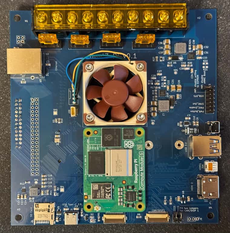
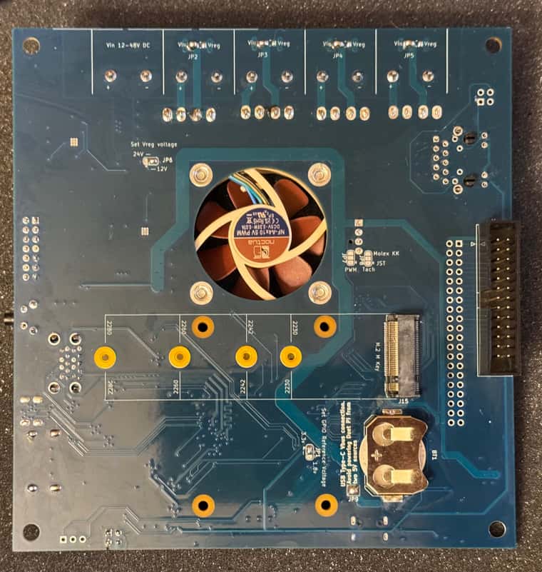
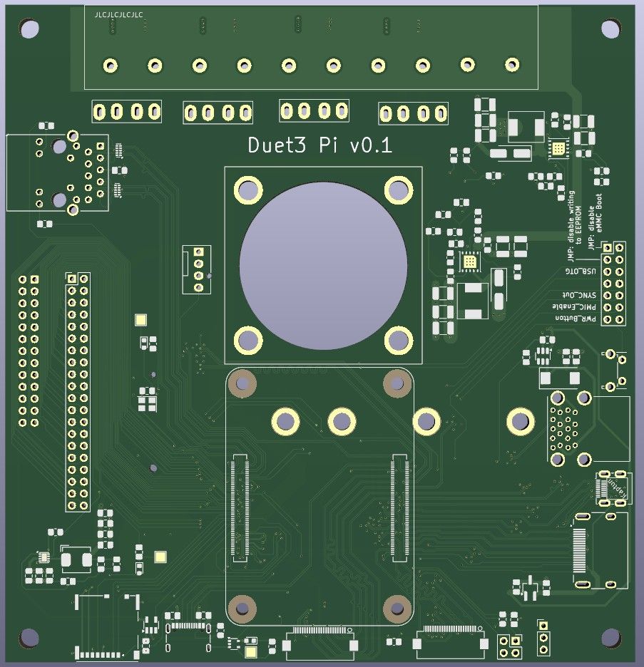
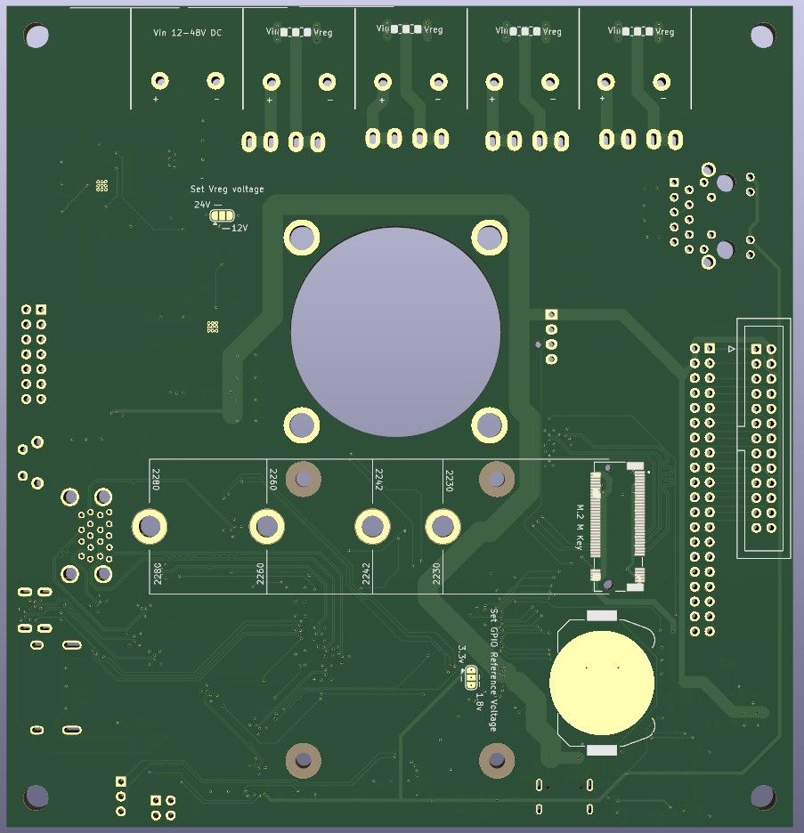
progress pics! (front and back view) It's coming together. I've got everything routed and the design rules checker is happy. I'm going to take a couple more days to mull over some choices, maybe clean things up a little more and send this off to get fabbed! I'm sure there's one killer feature that I'm forgetting to add. Hopefully I think of it before then
")
You might notice that I gave up on the idea to sandwich the CM5 in-between the boards. It seemed like an elegant idea in my head, but in practice the layout/routing wasn't making sense to me. The CM5 will probably be happier in open air with a passive heatsink anyways.
-
I've fired off my order to for the pcb and components!
I've also cleaned up the design files good enough to publish if anyone is curious or wants to critique:
https://github.com/taegge/duet_pi -
More progress! I'm still missing a few components, but the board is mostly populated. The 5v and 12v/24v regulators are performing well. I got brave and plugged a CM5 in this morning -- green light and no smoke! I haven't come across any major design issues yet (knock on wood).
I've stumbled a few places where my old lead-free solder past didn't flow as well as needed, but have been able to diagnose and rework those issues. The mini-hdmi connector is a huge pain with its hidden row of contacts. I probably won't bother populating this on any other boards I make as it's pretty redundant with the two DSI/CSI and single full sized hdmi connectors.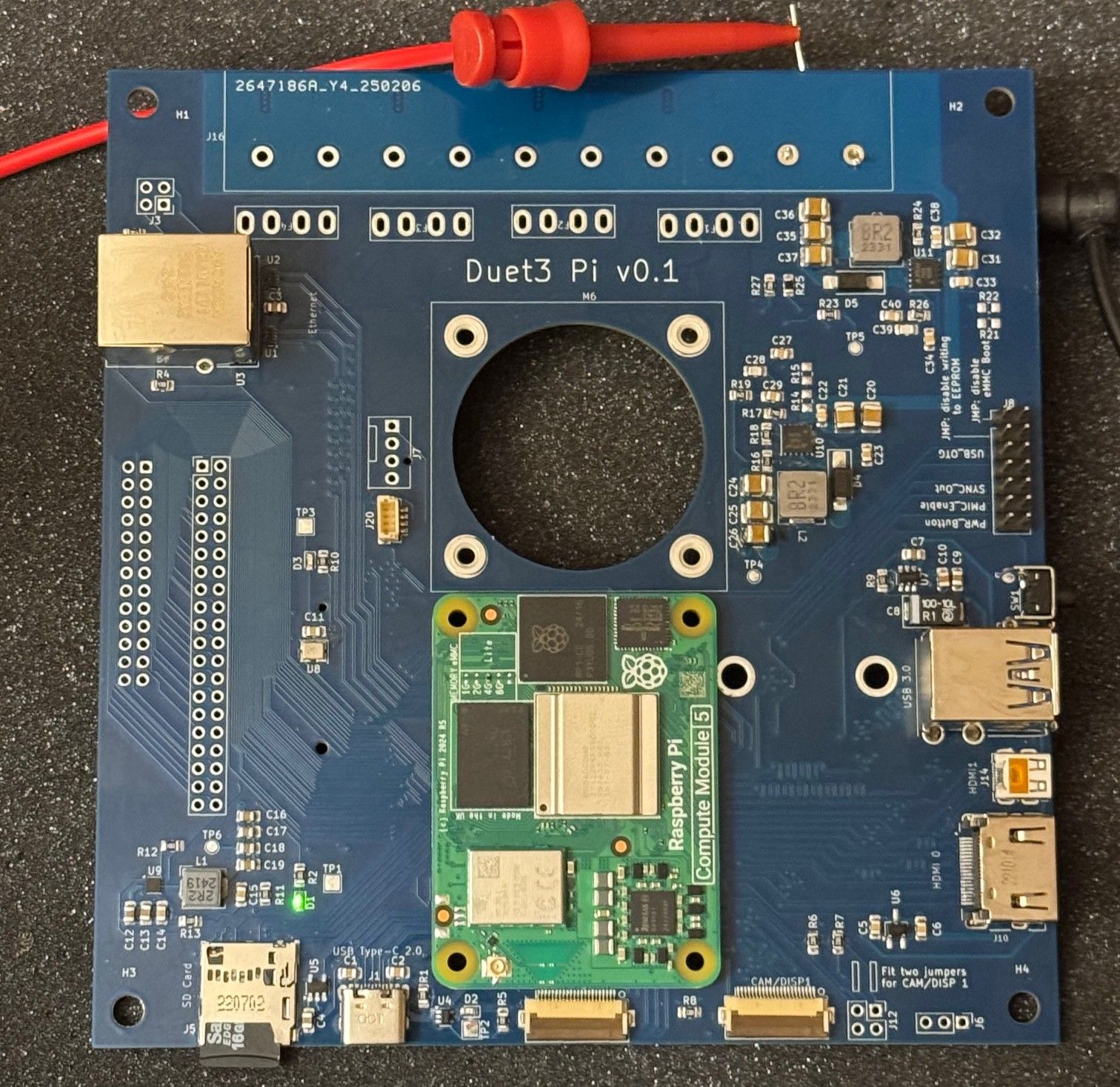
-
My vision is almost fully realized! I must have jinxed myself in my last post. No show stoppers, but have hit a couple issues:
1- you might notice the ethernet jack isn't soldered. It's just dry-fit for show right now. I removed it after realizing that my part didn't match the footprint i used. It was a physical fit, but pins were wrong. I could only find the matching part overseas, so still waiting. I intend to update the schematic/layout to use a more common magjack. In the meantime wireless is working great.
2- the 12v/24v regulator isn't behaving all the way up to 5A. It's fine up to 3A, but starts cutting out above 4A. I forgot to upgrade the inductor and diode when I moved my target from 3A to 5A. That's probably part of it. I need to take another look at the layout too. Thankfully 5v appears reliable all the way up to 5A. The printer i'm going to test this out on doesn't need the aux supply, so no biggie for now.
3 - when I added the Molex KK PC style fan header, I mistakenly assumed the Pi5's 4 pin connector followed the same standard. Nope. Easy fix. Happy accident to get to trim the wires down and solder in the correct places. (I guess I could have rearranged the connectors too, but ick)Next step is to actually connect to a Duet3