My vision is almost fully realized! I must have jinxed myself in my last post. No show stoppers, but have hit a couple issues:
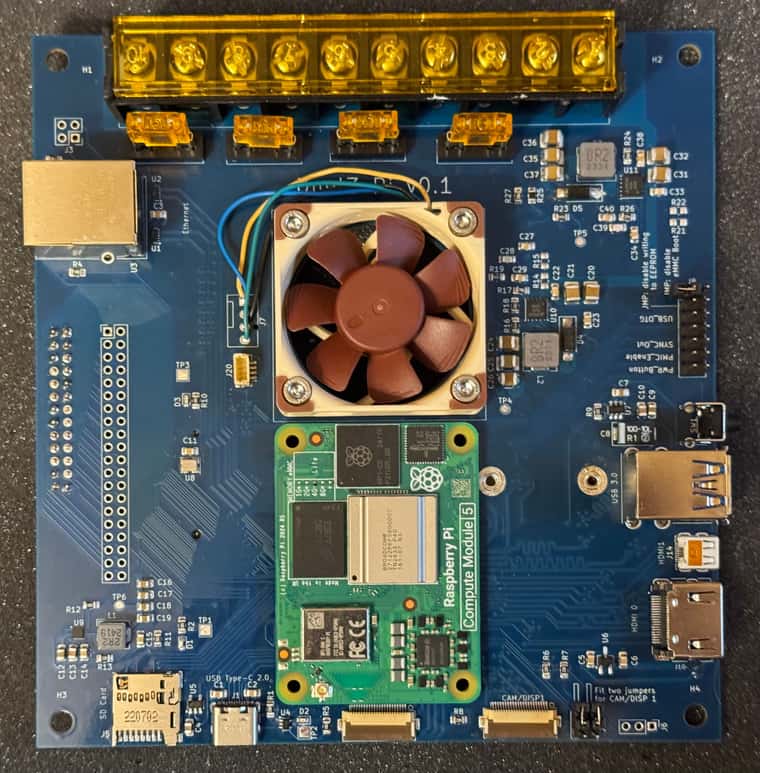
1- you might notice the ethernet jack isn't soldered. It's just dry-fit for show right now. I removed it after realizing that my part didn't match the footprint i used. It was a physical fit, but pins were wrong. I could only find the matching part overseas, so still waiting. I intend to update the schematic/layout to use a more common magjack. In the meantime wireless is working great.
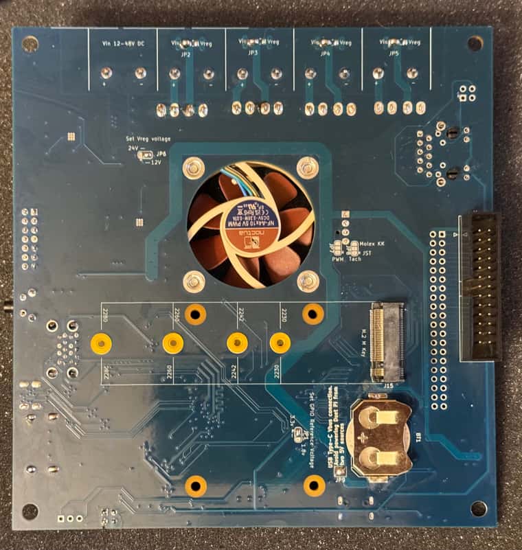
2- the 12v/24v regulator isn't behaving all the way up to 5A. It's fine up to 3A, but starts cutting out above 4A. I forgot to upgrade the inductor and diode when I moved my target from 3A to 5A. That's probably part of it. I need to take another look at the layout too. Thankfully 5v appears reliable all the way up to 5A. The printer i'm going to test this out on doesn't need the aux supply, so no biggie for now.
3 - when I added the Molex KK PC style fan header, I mistakenly assumed the Pi5's 4 pin connector followed the same standard. Nope. Easy fix. Happy accident to get to trim the wires down and solder in the correct places. (I guess I could have rearranged the connectors too, but ick)
Next step is to actually connect to a Duet3 ")