Mesh bed compensation, poor first layer?
-
I have been having problems getting mesh bed compensation working well. The first layer always seem inconsistent. I have 2 printers running on Duet3 6HC boards and both have problems getting a perfect first layer, so it may be an issue with how I am setting them up.
One is a converted Anycubic Kobra 2 Max, with this I thought it may be an issue with the inductive z probe not being consistent, but I have changed this for a Duet IR z probe and the results are the same. I have taken to modifiying the generated height map in a spreadsheet with a set of modifiers for each point which gets me much closer to a good first layer, but not perfect.
The other printer which I am now trying to calibrate also has issues with a consistent first layer, in some areas the nozzle is clearly too far away from the bed and in others the nozzle is practically touching the bed. I can see that the z motors are moving which implies that mesh compensation is active, but not working very well.
This printer uses a bl touch z probe and I have calibrated the height offset to give a reasonable height for the start of the first layer, setting the z offset exactly the correct value when the nozzle is at exactly 0 height does not work well for the first layer height.
The printer has 2 independant z motors on each side of the bed and are each levelled when the axis are homed.I add a 'G29 S1' to the start code in the slicer to enable mesh compensation for each job.
Any help on what I am doing wrong is appreciated.
bed.g
28 ; home
while true
    G30 P0 X0 Y150 Z-99999 ; probe near a leadscrew, half way along Y axis
    G30 P1 X252 Y150 Z-99999 S2 ; probe near a leadscrew and calibrate 2 motors
    if abs(move.calibration.initial.deviation) < 0.01 || iterations > 4
        break
homeall.g
M561       ; Cancel any currently active mesh compensation

; lift Z
G91                                                   ; relative positioning
G1 H2 Z5 F6000                                        ; move Z relative to current position to avoid dragging nozzle over the bed
G90                                                   ; absolute positioning

; home XY
var xTravel = move.axes[0].max - move.axes[0].min + 5 ; calculate how far X can travel plus 5mm
var yTravel = move.axes[1].max - move.axes[1].min + 5 ; calculate how far Y can travel plus 5mm
G91                                                   ; relative positioning
G1 H1 X{var.xTravel} Y{var.yTravel} F9000             ; coarse home in the +X and +Y directions
G1 H2 X-5 Y-5 F6000                                   ; move back 5mm
G1 H1 X{var.xTravel} Y{var.yTravel} F300              ; fine home in the +X and +Y directions
G90                                                   ; absolute positioning

; home Z
; NOTE: The following XY coordinates use values from the probe grid defined in the next section
var xCenter = move.compensation.probeGrid.mins[0] + (move.compensation.probeGrid.maxs[0] - move.compensation.probeGrid.mins[0]) / 2 - sensors.probes[0].offsets[0]
var yCenter = move.compensation.probeGrid.mins[1] + (move.compensation.probeGrid.maxs[1] - move.compensation.probeGrid.mins[1]) / 2 - sensors.probes[0].offsets[1]
G1 X{var.xCenter} Y{var.yCenter} F9000                ; go to bed centre
G30

while true
    G30 P0 X0 Y150 Z-99999 ; probe near a leadscrew, half way along Y axis
    G30 P1 X252 Y150 Z-99999 S2 ; probe near a leadscrew and calibrate 2 motors
    if abs(move.calibration.initial.deviation) < 0.02 || iterations > 4
        break

; home Z again after independently levelling each of the 2 z axis motors
G1 X{var.xCenter} Y{var.yCenter} F9000                ; go to bed centre
G30                                                   ; probe the bed
config.g
G90                 ; absolute coordinates
M83                 ; relative extruder moves
M550 P"folgertech5" ; set hostname

M575 P1 B57600 S1 ; configure PanelDue support

M569 P0.0 S1 D2             ; driver 0.0 goes forwards (extruder 0)
M569 P0.1 S1 D2             ; driver 0.1 goes forwards (X axis)
M569 P0.2 S0 D2             ; driver 0.2 goes forwards (Y axis)
M569 P0.3 S0 D2             ; driver 0.3 goes forwards (Y axis)
M569 P0.4 S1 D2             ; driver 0.4 goes forwards (Z axis)
M569 P0.5 S0 D2             ; driver 0.5 goes forwards (Z axis)

M906 X1400 Y1400 Z1200 E1400 ; set motor driver currents

M584 X0.1 Y0.2:0.3 Z0.5:0.4 ; set axis mapping
M350 X16 Y16 Z16 I1         ; configure microstepping with interpolation

M92 X80 Y80 Z3200           ; configure steps per mm
M208 X0:290 Y0:290 Z0:350   ; set minimum and maximum axis limits
M566 X900 Y900 Z60          ; set maximum instantaneous speed changes (mm/min)
M203 X12000 Y12000 Z1200      ; set maximum speeds (mm/min)
M201 X2200 Y2200 Z900       ; set accelerations (mm/s^2)

M584 E0.0   ; set extruder mapping
M350 E16 I1 ; configure microstepping with interpolation
M92 E830    ; configure steps per mm
M566 E600    ; set maximum instantaneous speed changes (mm/min)
M203 E600   ; set maximum speeds (mm/min)
M201 E1600   ; set accelerations (mm/s^2)

M558 K0 P9 C"io4.in" H5 F120 T6000 ; configure BLTouch probe via slot #0
G31 P500 X-34 Y0 Z2.84             ; 2.22 measured, set Z probe trigger value, offset and trigger height, higher numbers move nozzle closer
M950 S0 C"io4.out"                 ; create servo #0 for BLtouch

M574 X2 P"!io1.in" S1 ; configure X axis endstop
M574 Y2 P"!io2.in" S1 ; configure Y axis endstop
M574 Z1 S2            ; configure Z axis endstop

M671 X-100:400 Y150:150 S5.0 ; position of leadscrew/bed pivot point at left and right of X axis

M308 S0 P"temp0" Y"thermistor" A"Heated Bed" T100000 B4066      ; configure sensor #0
M308 S1 P"temp1" Y"thermistor" A"Nozzle" T100000 B4388 C7.06e-8 ; configure sensor #1

M950 H0 C"out0" T0                                      ; create heater #0
M143 H0 P0 T0 C0 S120 A0                                ; configure heater monitor #0 for heater #0
M307 H0 R0.206 K0.163:0.000 D3.20 E1.35 S1.00 B0        ; configure model of heater #0
M950 H1 C"out1" T1                                      ; create heater #1
M143 H1 P0 T1 C0 S300 A0                                ; configure heater monitor #0 for heater #1
M307 H1 R1.930 K0.293:0.133 D8.50 E1.35 S1.00 B0 V24.1  ; configure model of heater #1

M140 P0 H0                                ; configure heated bed #0

M950 F0 C"out8"                           ; create fan #0
M106 P0 C"Part Cooling Fan" S0 L0 X1 B0.1 ; configure fan #0
M950 F1 C"out7"                           ; create fan #1
M106 P1 C"Hot End Fan" S0 B0.1 H1 T45     ; configure fan #1
M950 F2 C"out9" Q10000                    ; configure out9 to control led lighting
M106 P2 C"Bed Lighting" S0 H-1

M563 P0 S"Print Head" D0 H1 F0 ; create tool #0
M568 P0 R0 S0                  ; set initial tool #0 active and standby temperatures to 0C

M591 D0 P3 C"io5.in" S1 R50:120  ; filament monitor

;M955 P0 C"spi.cs1+spi.cs0" I60  ; accelerometer, all wires connected to temp DB connector
M593 P"zvddd" F36  S0.1  ; configure input shaping

M557 X4:286 Y4:286 S40:40 ; define grid for mesh bed compensation, note: these are the probe positions not the nozzle
;G29 S2                    ; disable mesh bed compensation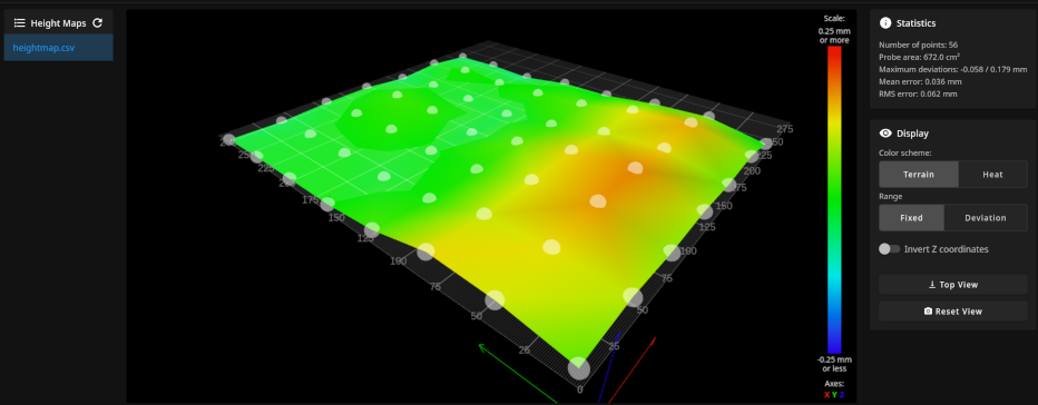
-
@bug2k22 said in Mesh bed compensation, poor first layer?:
M584 X0.1 Y0.2:0.3 Z0.5:0.4
I notice that your z driver mapping uses 5 and then 4. Note that the order of the motors here must match the order of the lead screw positions in your m671 command.
@bug2k22 said in Mesh bed compensation, poor first layer?:
M671 X-100:400 Y150:150 S5.0 ; position of leadscrew/bed pivot point at left and right of X axis
Your tilt correction may not be behaving as expected.
https://docs.duet3d.com/en/User_manual/Connecting_hardware/Z_probe_auto_levelling
-
@Phaedrux I will check the wiring and see if I do have them wired opposite to the levelling assignment.
As noted in the original post, I also have another printer which drives phyisically linked z motors (i.e. the act as one) and this exhibits the same issues with regard to poor mesh bed compensation.I have since mapped a grid of the differences between the probed z heights and the actual compensation that is required and this works well, but means I have to copy the probed grid offsets into a spreadsheets which applies a fixed offset to each point and then paste this back in to the mesh compensation file on the duet.
-
Typically in cases like this the cause is a physical/mechanical issue causing some unintended movement of the print head. Either some sag in the gantry, or rails being skewed or twisted to the XY plane. A small amount of tilt on the print head causes the probe offset and trigger height to change in relation to XY position so the map is distorted.
One way to check this is to switch the probe type to P0 which is manual probing and re-run G29 to create a map using the nozzle as the probe. It's slow to manually probe each point, but the resulting mesh should be accurate to the actual nozzle position.
-
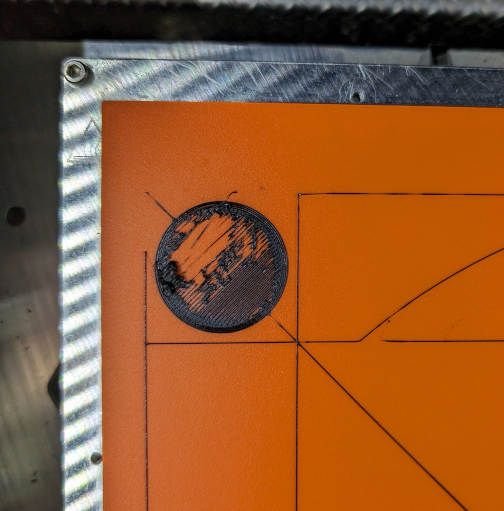
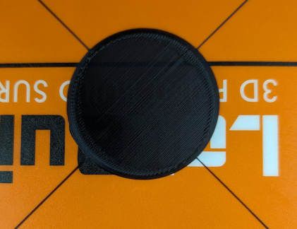
Just a brief follow up to this, I never could get a good first layer with this setup. I tried with a bltouch, inductive and IR sensors all gave similar results, the first layer was very inconsistent.
I have now installed a dyze designs horizon z probe which uses the nozzle for z probing, mesh bed compensation now works as expected and I get very good, consistent first layers.