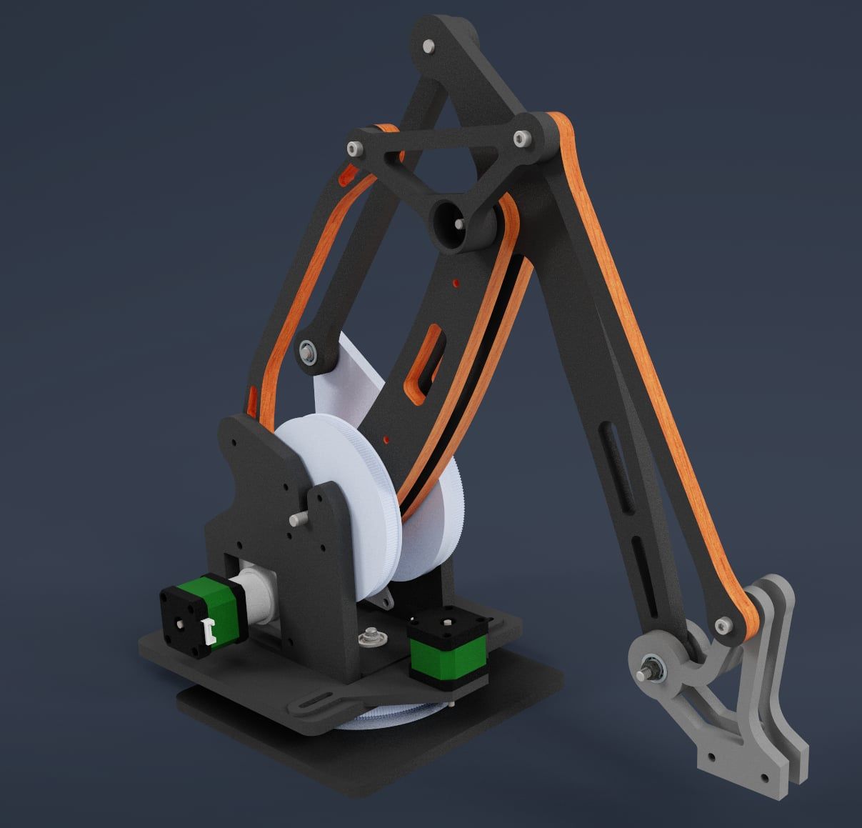
4 axis palletized robot arm (robot kinematics) for 3D printing
-
@Nakcam the kinematics is not implemented yet, but I'll try to do it with your help.
Please confirm or correct me:
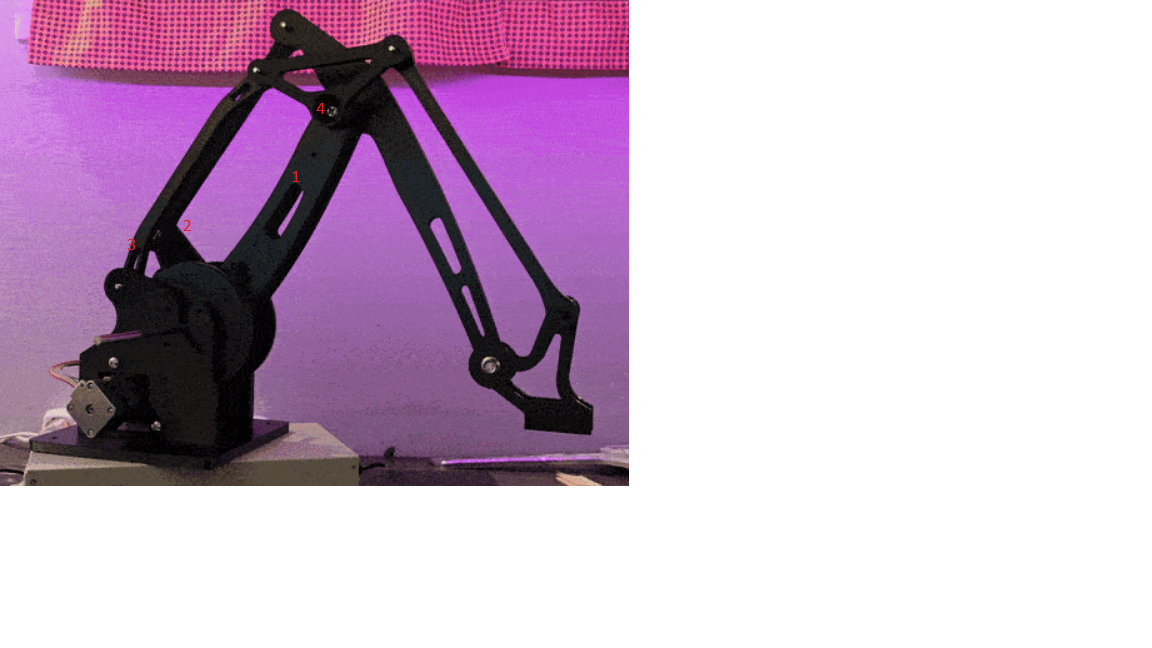
- 1 is connected with first actuator/stpper
- 2 is connected with the other
- 3 is connected to base
- 4 is a hinge connecting three parts: tringle low, big arm and other big arm
Your short video looks like the front horizontal platform tilts a bit, the front going a bit down. This may be an optical illustion. But if it's real, then some of the angles are wrong and the construction is not a parallelogram. Maybe you'll need to change the prototype a bit. But let's make the kinematics first.
BTW I like your prototype, because the gear is belt based, which means low or no backlash. The planetary based gears have some play when changing orientation of the rotations.
-
@JoergS5 Thanks for helping out! You are correct on how the linkage work (point 1-4). The platform is tilted a bit, but the tilt does not change when moving (it does a tiny bit but that's because of sloop in the system, i did not have all the right fasteners at hand). I am working on a updated version that uses Capstan-Drive system. I would like to get this working first.
here's a fusion 360 link to the cad model
a360.**/42M19T2in using 1.8degree steppers and total gearing is 51,8 (5,18:1+200:20)
-
@Nakcam I can work next weekend on it, and it would be nice if you can make some tests with the prototype, verifiying code, while I develop the code. I can provide you the RRF binary for each test.
-
@JoergS5 Sounds great! Is there some "hack" to force the D values for now? Or is the robot firmware on github not working?
-
@Nakcam the D values make only sense when the axes are calculated in the chain. This is only implemented for CoreXY. I you want to test setting D values in advance, just define your config for CoreXY.
-
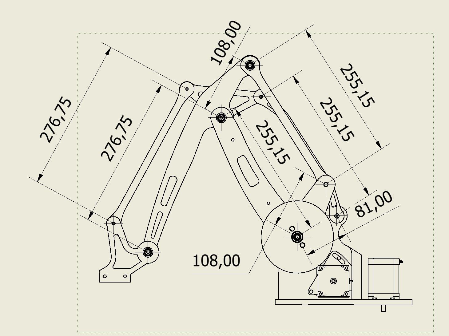
@JoergS5 Ok. I will wait for your test bin files then. here is some dimensions of my arm
-
@Nakcam thank you! I don't have Fusion, so from your image I can make a prototype as well.
Please measure the triangle lenghts as well, from hinge to hinge each.
-
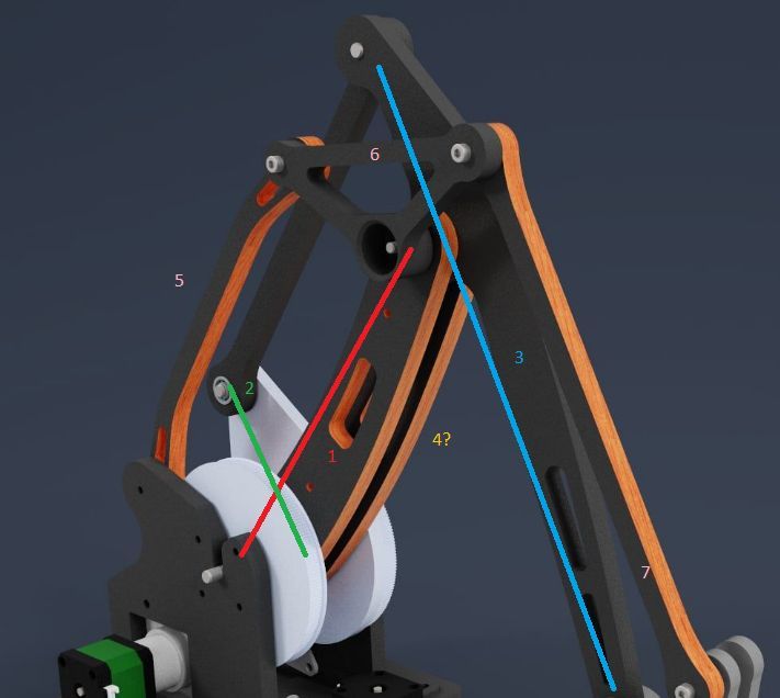
@Nakcam here is a short explanation of the parallelograms:
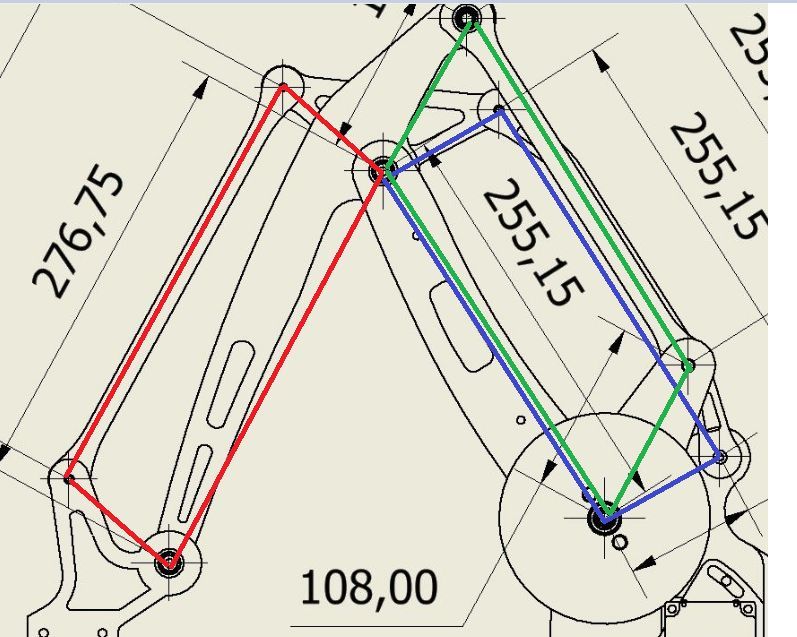
The blue and red ones are connected through the triangle. The triangle is like a curve of the arms from up to down.
The opposite sides of blue, red and green parallelograms shall be parallel each. When they become "flat", i.e. small angles and opposite sides near at each other, the movements and caluclations will become inexact. So this situations should be avoided.
-
@JoergS5
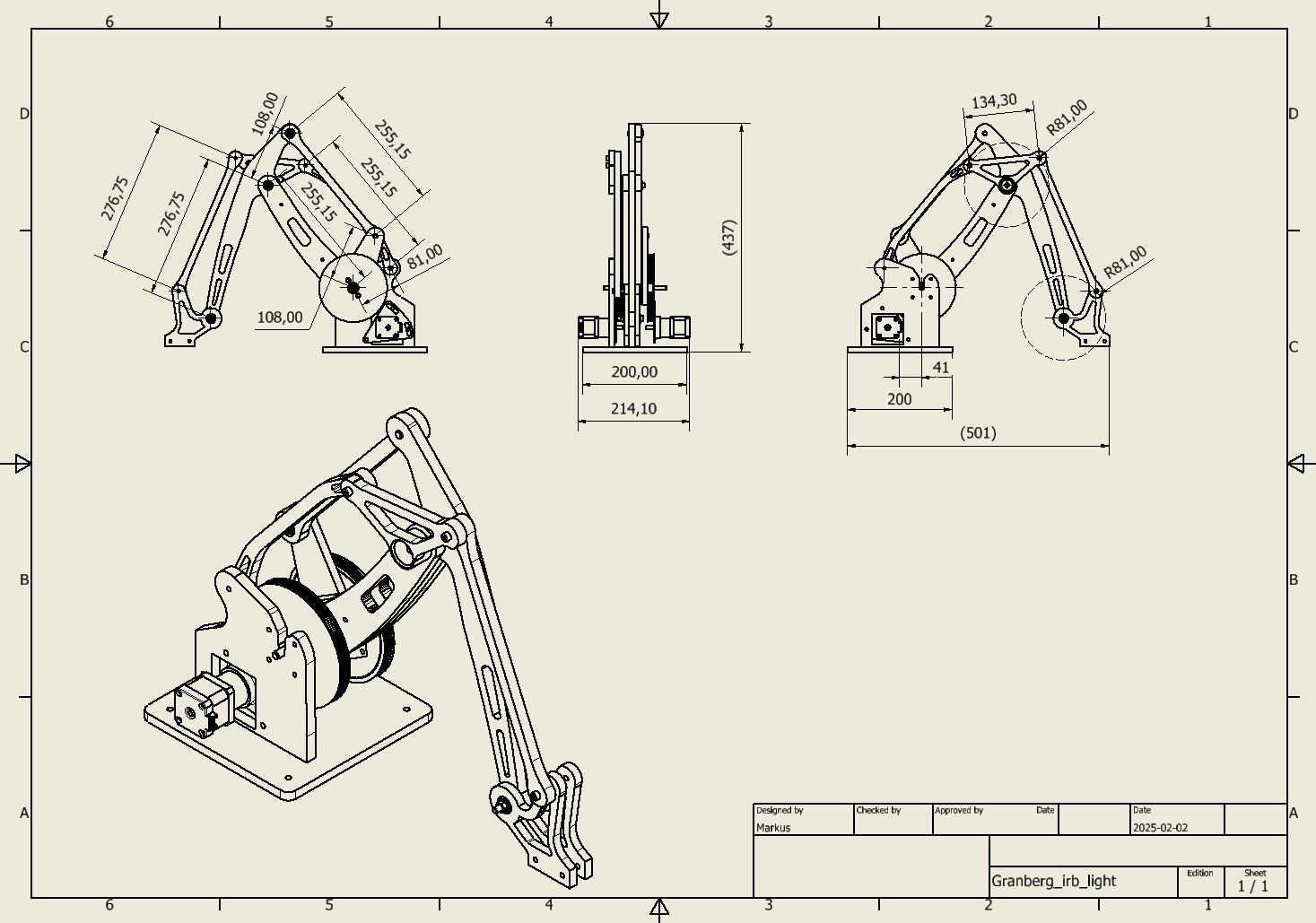
Here is a better drawing. Is there som cad format that you prefer? I can export to most of them. would you suggest any changes to the geometry? -
@Nakcam thanks a lot, I hope this is sufficient information for now to start. After the firmware runs, we can discuss improvements if you like. As always it will depend on what you want to do with it whether it's worth to improve precision etc.
This remembers me of that I need a load lifter, maybe I'll build it this this kinematics. Similar to a IRB 760.
-
@JoergS5 My plan is to use this robot to reload my resin printer, so the final version should be capable to handle about 1.5kg. it will be mounted on a linear rail. Repetability will be more important than absolut precision.
I do own a cnc mill and the final version might be in aluminium or laser cut plywood. But its 3d printed for now -
I have added a rotational axis nr1 to the base.
-
@Nakcam sorry for the delay. I had a family problem, I'll try to proceed.
I want to clearify, please tell me:
My understanding is:
- 1 is the first actuator
- 2 is the second one. Together they define through the parallelogram the blue arm and the lower end position, lower hinge
- 4 (the second arm in back of 1) is unclear for me: is it just to stabilize or has it a movement function?
- 5, 6 and 7 define the upper endpoint in respect to the lower endpoint through parallelism
Is my understanding correct?
Comment in advance to the linear rail where you plan to install it on: this fits perfect into a calculation chain, but you have 4 actuators and 3 degrees of freedom (xyz, orientation always the same). This results in indefinite solutions (you can reach a point with different combinations of linear rail and the 3 actuators), i.e. for a desired position there must be installed a strategy. E.g. if the planned coodination is out of reach, move the linear rail to the middle of the new next work area. This movement should not be in a move, but between moves. I want to make something similar: some (5 or 6) robot arm installed on a linear rail at the wall.
-
@JoergS5 No problem.
1 is the first actuator / this is correct. If I add a rotating base to the robot does the rotating base become axis1? Or does it not matter?
2 is the second one. Together they define through the parallelogram the blue arm and the lower end position, lower hinge / This is correct. the link between 2 and the blue arm only moves the motor position down to the base, it has the same effect on blue arm 3 as if it was mounted in connection point between 1 and 3 (edit, the last bit is not correct, its only true if you add correction, ignore that part)
4 (the second arm in back of 1) is unclear for me: is it just to stabilize or has it a movement function? this is correct, arm1 and arm 4 is mechanically the same and can 4 is only strength
5, 6 and 7 define the upper endpoint in respect to the lower endpoint through parallelism /correct,The basic setup is verry similar to a abb irb660 (specially now that i have added the rotating base).
I cant post url links here for some reason. but add youtube. com to the url below to watch a irb660 in motion.watch?v=8LJOLwr5Wck
-
@Nakcam thank you for clearification.
Robot kinematics is based on a chain of the actuators: axes with position and orientation and arms between them. The endpoint is just an additional arm without axis. So you can add axes at the beginning and end, but inverse kinematics must be able to calculate it. Your rotating base is included in the 4 axis parallel robot type. Your linear axis at the beginning is something additional. The robot type sometimes has an additional actuator at the endpoint, for rotation of the end plate or for a gripper.
I proceed tomorrow to develop, because I feel that I have understood it now. I will develop with the blue line being curved optionally. (not a straight line between the three hinges of the blue line).
-
@JoergS5 Do you have access to a 3d printer big enough for printing my design?
-
@Nakcam it's all fine with your information, I have "only" a time problem. I can proceed tomorrow for a few hours.