Duet3D Logo Duet3D
    • Tags
    • Documentation
    • Order
    • Register
    • Login

    Laser Output

    Scheduled Pinned Locked Moved
    Laser Cutters
    4
    25
    653
    Loading More Posts
    • Oldest to Newest
    • Newest to Oldest
    • Most Votes
    Reply
    • Reply as topic
    Log in to reply
    This topic has been deleted. Only users with topic management privileges can see it.
    • jay_s_ukundefined
      jay_s_uk @Macwolf
      last edited by

      @Macwolf try wiring the laser fire pin to the negative of out0, 1 or 2 and change your config accordingly.
      you can see more detailed wiring for the K40 here https://github.com/TeamGloomy/LPC-STM32-RRFUserConfigs/tree/master/K40 CO2 Laser - SKR 2 - ESP - paulg4h to see if that marries up with your machine

      Owns various duet boards and is the main wiki maintainer for the Teamgloomy LPC/STM32 port of RRF. Assume I'm running whatever the latest beta/stable build is

      Macwolfundefined 2 Replies Last reply Reply Quote 0
      • Macwolfundefined
        Macwolf @jay_s_uk
        last edited by

        @jay_s_uk
        A technical question: How much frequency does a 40W CO2 laser tube need? In your example, is the Q value 5000? Or does that not matter.
        I am new to this area and am wondering whether I am implementing it technically correctly. There were no operating instructions included, neither with the power supply nor with the tube.

        Markus

        jay_s_ukundefined 1 Reply Last reply Reply Quote 0
        • jay_s_ukundefined
          jay_s_uk @Macwolf
          last edited by

          @Macwolf IIRC, the 5KHz came from previously available information from when people were converting the K40 away from the original controller to boards that use GRBL etc

          Owns various duet boards and is the main wiki maintainer for the Teamgloomy LPC/STM32 port of RRF. Assume I'm running whatever the latest beta/stable build is

          1 Reply Last reply Reply Quote 0
          • Macwolfundefined
            Macwolf @jay_s_uk
            last edited by Macwolf

            @jay_s_uk
            Out 1 is now the output for the laser, it doesn't deliver a negative signal, does it?

            further connections are needed.

            1. 5V for TH

            2. ground

            3. I simulate the cooling.

            where exactly should I connect these cables to the power supply terminal
            Bildschirmfoto 2025-02-07 um 15.33.21.png

            dc42undefined 1 Reply Last reply Reply Quote 0
            • dc42undefined
              dc42 administrators @Macwolf
              last edited by

              @Macwolf said in Laser Output:

              Out 1 is now the output for the laser, it doesn't deliver a negative signal, does it?

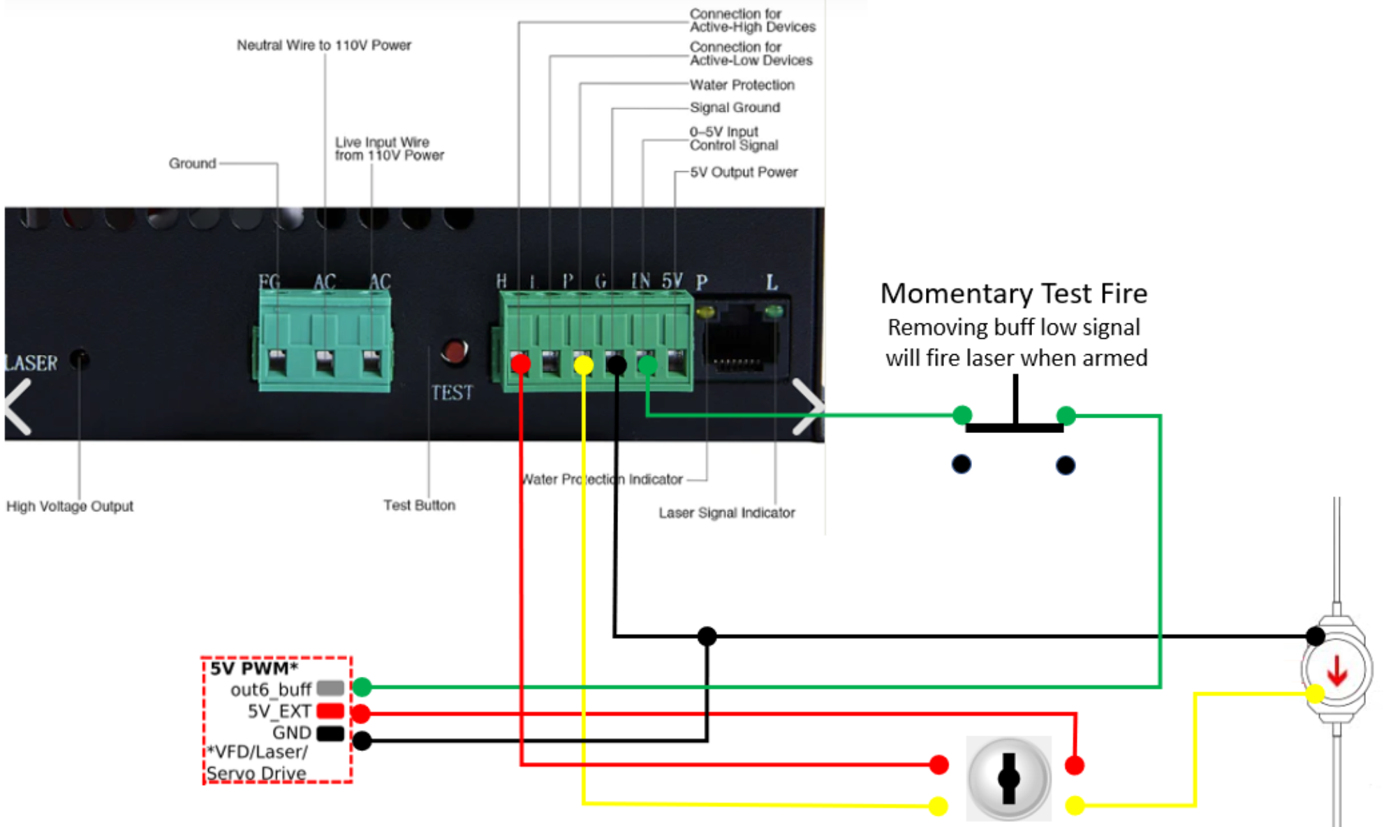
              OUT1 is an open-drain output, suitable for connecting to an active low input with internal pullup on the laser module.

              The output on the VFD/Laser connector is active high, suitable for connecting to an active high input on the laser module. It should be low when the Duet is powered on. However, when no power is supplied to the Duet you may find that it floats high enough to trigger the laser. if that happens then try connecting a 1K pulldown resistor between the output and ground.

              What type of control input does your laser module have?

              Duet WiFi hardware designer and firmware engineer
              Please do not ask me for Duet support via PM or email, use the forum
              http://www.escher3d.com, https://miscsolutions.wordpress.com

              Macwolfundefined 1 Reply Last reply Reply Quote 0
              • Macwolfundefined
                Macwolf @dc42
                last edited by

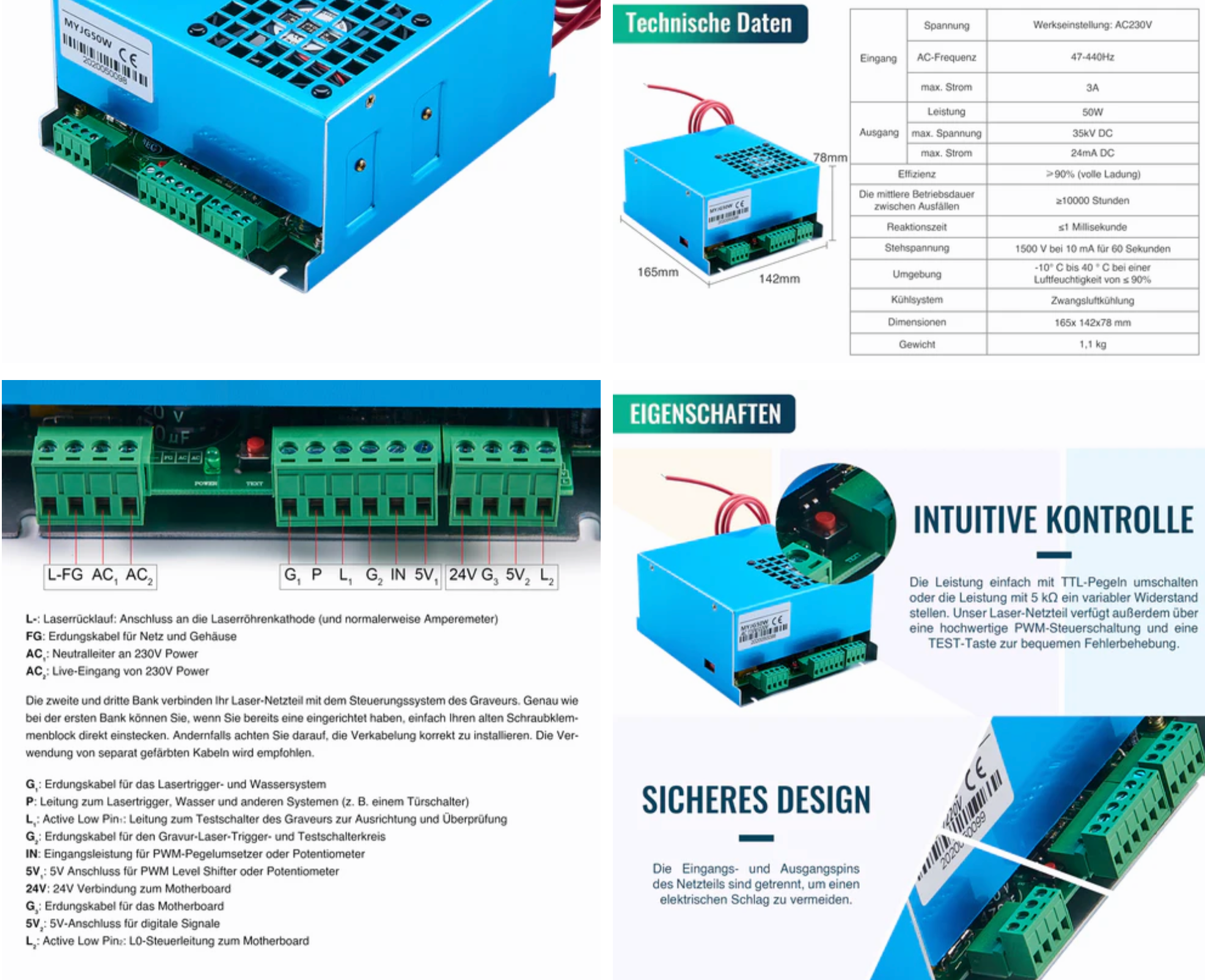
                @dc42 my power supply is from the same manufacturer as the tube I have a diagram, but the description is in GermanBildschirmfoto 2025-02-09 um 16.22.00.png

                jay_s_ukundefined 1 Reply Last reply Reply Quote 0
                • jay_s_ukundefined
                  jay_s_uk @Macwolf
                  last edited by

                  @Macwolf thats the same as PSU type 1 shown in the wiring diagram on the page I linked you to earlier (https://github.com/TeamGloomy/LPC-STM32-RRFUserConfigs/tree/master/K40 CO2 Laser - SKR 2 - ESP - paulg4h) so it would be wired in the same way i.e. to heater ground

                  Owns various duet boards and is the main wiki maintainer for the Teamgloomy LPC/STM32 port of RRF. Assume I'm running whatever the latest beta/stable build is

                  Macwolfundefined 1 Reply Last reply Reply Quote 0
                  • Macwolfundefined
                    Macwolf @jay_s_uk
                    last edited by

                    @jay_s_uk yes that's true, but there is no line from the contacts to the board and I don't want to try until it works

                    jay_s_ukundefined 1 Reply Last reply Reply Quote 0
                    • jay_s_ukundefined
                      jay_s_uk @Macwolf
                      last edited by

                      @Macwolf to the "L" connection like the PSU type 2

                      Owns various duet boards and is the main wiki maintainer for the Teamgloomy LPC/STM32 port of RRF. Assume I'm running whatever the latest beta/stable build is

                      Macwolfundefined 1 Reply Last reply Reply Quote 0
                      • Macwolfundefined
                        Macwolf @jay_s_uk
                        last edited by

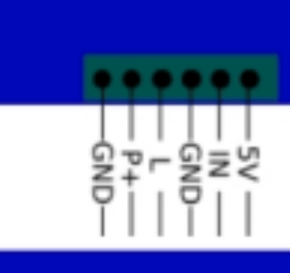
                        @jay_s_uk and the others there are more connections like 5v, p+ gnd ......where are these connected to the duet board?

                        jay_s_ukundefined 1 Reply Last reply Reply Quote 0
                        • jay_s_ukundefined
                          jay_s_uk @Macwolf
                          last edited by

                          @Macwolf which others are you talking about?

                          Owns various duet boards and is the main wiki maintainer for the Teamgloomy LPC/STM32 port of RRF. Assume I'm running whatever the latest beta/stable build is

                          Macwolfundefined 1 Reply Last reply Reply Quote 0
                          • Macwolfundefined
                            Macwolf @jay_s_uk
                            last edited by

                            @jay_s_uk Bildschirmfoto 2025-02-18 um 10.07.32.png

                            jay_s_ukundefined 1 Reply Last reply Reply Quote 0
                            • jay_s_ukundefined
                              jay_s_uk @Macwolf
                              last edited by

                              @Macwolf do you see those connected anywhere on the PSU type 2 to the SKR2 board?

                              Owns various duet boards and is the main wiki maintainer for the Teamgloomy LPC/STM32 port of RRF. Assume I'm running whatever the latest beta/stable build is

                              Macwolfundefined 1 Reply Last reply Reply Quote 0
                              • Macwolfundefined
                                Macwolf @jay_s_uk
                                last edited by

                                @jay_s_uk no only these control the tube

                                jay_s_ukundefined 1 Reply Last reply Reply Quote 0
                                • jay_s_ukundefined
                                  jay_s_uk @Macwolf
                                  last edited by

                                  @Macwolf ok then. so you just need to connect the "L" connection to the duet. You will need to connect a ground connection, like on PSU type 2, to your power supply powering your duet

                                  Owns various duet boards and is the main wiki maintainer for the Teamgloomy LPC/STM32 port of RRF. Assume I'm running whatever the latest beta/stable build is

                                  1 Reply Last reply Reply Quote 0
                                  • First post
                                    Last post
                                  Unless otherwise noted, all forum content is licensed under CC-BY-SA