Vertical banding
-
While I don't have any idea as to what's causing this, you can probably speed up your troubleshooting time by simply taping a sharpie marker to your hotend, and doing a test print drawing on a piece of paper instead of actually extruding anything: That should show the wobble I presume. If this was z-banding you'd need to actually print a tower. But since this is an XY wobble, you may give the sharpie method a go: I see people taping them to their CNC's to draw stuff… seems like it may apply here.
-
Hehe, well I think i found my problem…. I was testing one thing at a time. It took the combined effort of boosted stepper current, 0.9 steppers and smaller pulleys. I went from a 22mm diameter pulley to 14mm the line barely all fits on the spool, this is the result.


I challenge you to find the vertical lines:)
Heated bed should be here this week some time, it will be nice to get rid of the blue tape, tiny bed and warped print corners. If i had to pick one I would stay the steps per mm was the main issue (as dc42 noted), it seems things act funny at such a low step per mm. For a reference I was using 45 step/mm for most of my testing, 90 step/mm with the 0.9 steppers (still banding) and 140 with both the 0.9 steppers and 14mm pulley.Thanks everyone for the suggestions and ideas, I hope this thread will be useful to someone in the future:)
-
I'm glad you got it working.
It occurred to me that if the drivers have a problem with low current microstepping, this could also cause that banding. We don't normally see a problem with low current microstepping on the TMC2660 drivers in the Duet, whereas such problems are well-known with DRV8825 drivers. But if you were using a combination of low-inductance motors AND a low motor current, there could be a problem. In that case it would be necessary to adjust the chopper control register settings.
What is the specification of your motors, and what current do you have them set to in M906?
-
This is what i changed to https://www.sparkfun.com/products/10846
0.9 degree
3.06V
1.7A (operating at around 1.2A i think)
1.8 OHM
2.8 mHThis is what i had before:
KH4234-b95101
1.8 degree
3.41v
1.1A (operating at 0.55 A)
3.1 OHM
4.4 mHAfter work I will drop the current down a little bit and see if the banding comes back at all. Is the "chopper control register settings" something i can change without recompiling the F/W? If so I would be happy to test any settings you like.
-
Yes the chopper control register can be adjusted using an M command. However, finding the correct setting is tricky.
0.55A is well below the optimum range for the TMC2660, so that may have contributed to the banding. 1.2A is much better.
-
Congratulations! Looks really nice.
Just as a quick calculation of the life time of a high quality motor bearing mounted as you have it and a 200N load sideways. This means 100N cord tension @2000RPM.
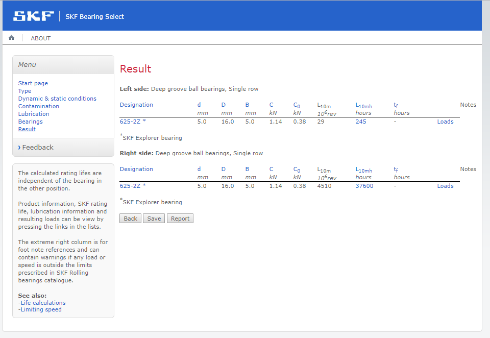
//P
-
Congratulations! Looks really nice.
Just as a quick calculation of the life time of a high quality motor bearing mounted as you have it and a 200N load sideways. This means 100N cord tension @2000RPM.
http://cadnicum.se/Bearing%20calc.png
//P
Forgive me if im missing your point but is this not how nearly 100% of all 3D printers mount the motors? I think we get more then 245 hours on them:)
-
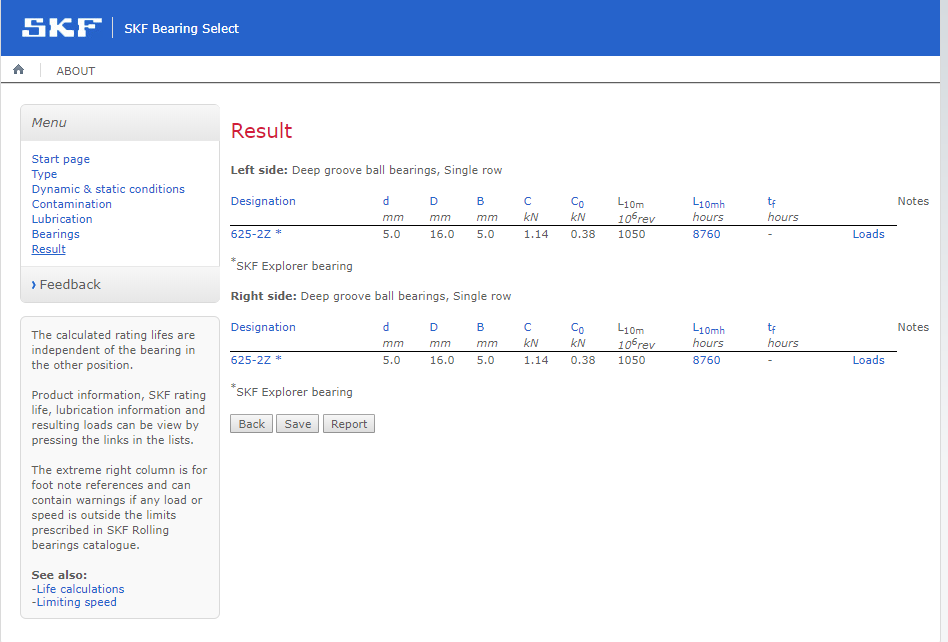
The point is that the mounting arrangement is not good. Just because it is done doesn't mean its good and life time of a bearing is not until it ceases to function or exist as a ball bearing. I know that 100N is in the high tension for most people and 2000 RPM is the upper speed for many steppers. Slower speed and repeated short back and forth motion can be really bad for bearings since the grease has problems forming a good film inside it at lower speeds.
Here is what happens if you do as I told you earlier and center the load between the ball bearings. All else the same. You can run with much harder tension and lower friction. That reduces ringing since the extra load due to the accelerated mass is smaller compared to the tension in the cord. This should be extra important for you since you have a very long thin free cord and hence a relatively elastic setup.
Loading a deep grove ball bearing axially is not that bad since it distribute the load on all included balls.
-
Got yea, thanks Perplexed, I will keep that in mind as my next task is to start the real tuning of accelerations, jerk, line tension and ringing now that i got the major defect out of the way.
On thing i have seen is that all my blue parts are made out of PETG and with the tall towers the idlers and motors are mounted on the parts flex a little bit, I might reprint them in Raptor high temp PLA, should reduce ringing a little. -
Yes the chopper control register can be adjusted using an M command. However, finding the correct setting is tricky.
0.55A is well below the optimum range for the TMC2660, so that may have contributed to the banding. 1.2A is much better.
I started the following print at 1.2A stepper current then dropped them to 0.45A part way in the print, its hard to see and even harder to photograph but you can detect a vary slight ripple start after reduced current change.
The bottom of the part is to the right hand side in the photo, the left most side of the black sharpy marks the location of the current change. Ignore the V shaped ripple at the bottom of the screen that is just ringing. If you look 1/3rd of the way up you will see a vary vary slight ripple that's not seen below (to viwers right) the sharpy mark line.

So while some systems (perhaps even my original motors) may be more sensitive i think that the low current was only a small part of the main issue of a low Steps/mm not behaving smoothly.
-
Thanks everyone, I think this has solved my problem as well - although it will be a few more weeks before my 0.9 steppers arrive.
A key detail is:
@Kezat:I was testing one thing at a time. It took the combined effort …
My 16x microsteps/mm was 53.33 using a 30 tooth GT2 pulley, so similar to Kezat's 45.35. I had one 16 tooth pulley to try and initially did not think it made any difference - but when I carefully counted the bands I got 8.4 in 10mm before and 4.5 in 10mm with the smaller pulley and higher current.
The 16t pulley took me to 100 steps/mm, so with 0.9 steppers I should get to 200 microsteps/mm.
Both the distance (mm) between bands and the steps/mm increased by 1.87x, so would say that this is exactly where the problem lies.
@Kezat:IThanks everyone for the suggestions and ideas, I hope this thread will be useful to someone in the future:)
Useful already in the present
")
-
That's great rob! Keep us updated when you get the 0.9 steppers installed.