Resurrecting fried Duet WiFi
-
After shaking off the first anger and shock (and ordering a new board) I started looking at the dead body. I evaluated my skills and chances of repairing the board and I think it's doable. I do however have a few mysteries to solve and would appreciate any help. Unfortunately I have no spare parts and need to establish if at all the project has a slightest chances of success. I may be taking a long shot here but I just can’t look at the fantastic piece of electronics lying dead, and want to make sure I did all I could before resting it in the grave
")
The cause of death was shorting 24V to 5V rail.
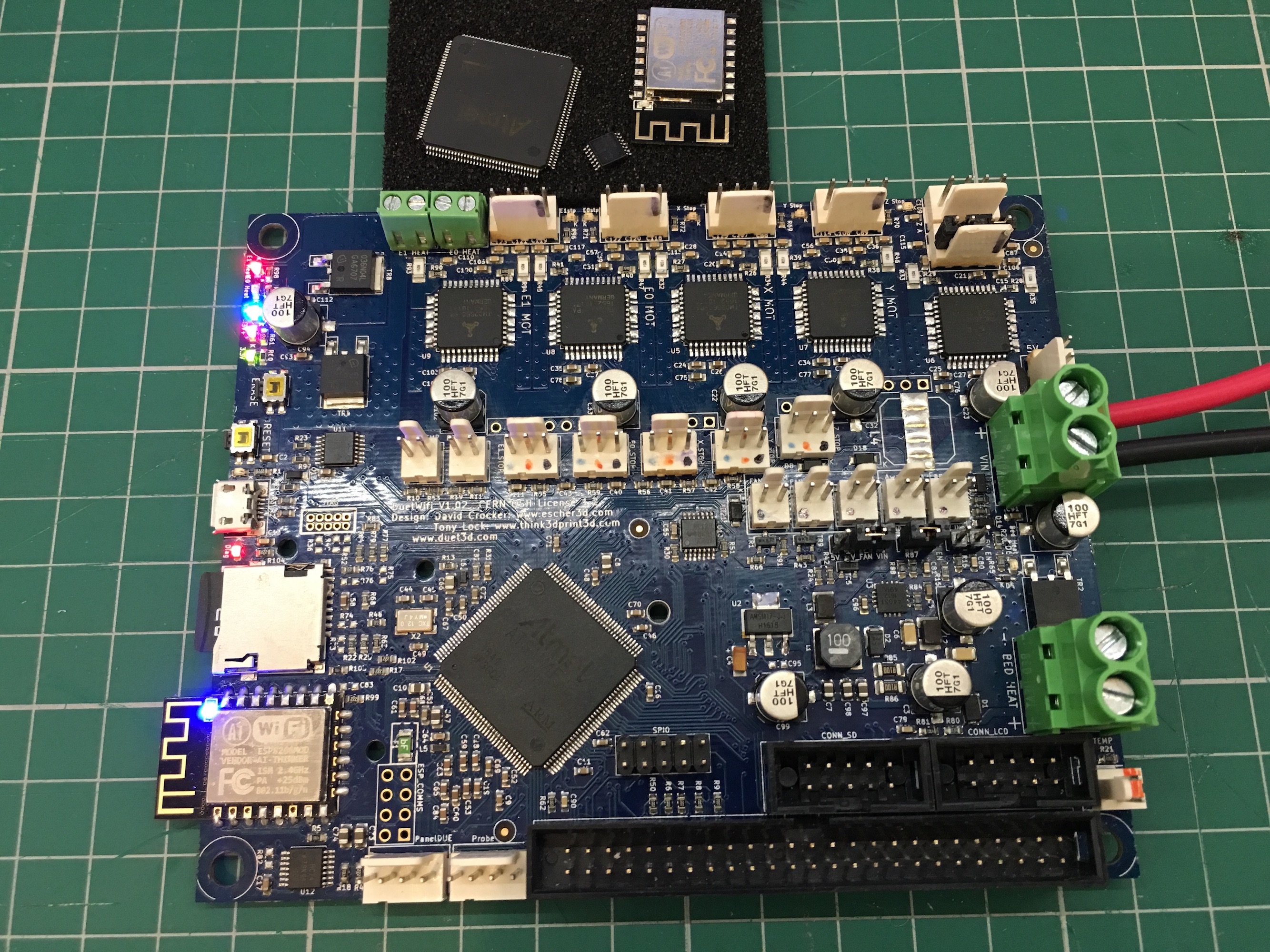
After replacing 3.3V regulator I identified the obvious parts to be replaced (they got hot) and removed them from the board.
- SAM4E (U1)
- 74HCT02 (U11)
- ESP module (U4)
Without those components the board draws about 80mA, which I think it’s fine. The 5V converter provides 4.91V, so seems within the margin. I examined and probed the rest of the components and they seem to react correctly (D flip-flop U12 and the buffer U10). The heater CMOS transistors also react when manually triggered with signals.
The big question remains about the TMC2660 drivers. I can’t find any supplier with stock so if they’re dead I won’t bother with the rest (for now). In the current shape I can’t test them. They seem OK, not burning or drawing excessive current, and also, if some of the other components survived maybe the drivers did too? The documentation says they require proper initialisation via SPI. I haven’t yet looked at any code to do that. First I need to hook them up to an external controller. The SPI1 signals are buffered by U10 and I would have to use the SAM4E pads as I can’t see any other pads. To prevent any damage to the traces I may be removing the U10 buffer and use the buffered rails on the extension socket. Would appreciate any suggestions if there are other methods.
The next question is the SAM4. I’m not too familiar with this family and may be taking a shortcut here. The SAM4E8E is in limited availability but SAM4E16E is available. I don’t know if there are any other differences than the amount of flash. In other words, would the latter get flashed the firmware fine or do I have to get the exact replacement?
The last part is the ESP module. The original is ESP12-F, which I believe differs from the E version only in antenna design. Would be the ESP-12E cause any problems?
And the last step is flashing both from zero. Are there any special steps required?
For now that’s all I got.
-
I can help with the parts, and as we are in email comms already. I'll get back to you that way
-
I can't help you regarding the TMC2660 drivers because I've never tried to repair a board that shows signs of a short from 24V to 5V.
The tantalum capacitor on the output of the 3.3V regulator may have failed too. SAM4E16E should work fine I think, as long as Bossa supports it (I haven't checked). For the WiFi module I suggest ESP-12S, or ESP-07S plus external antenna.
-
Thank you David for the tip. I missed the capacitor but will surely replace it. Thanks to Roland I should get the original replacements so I will not be risking testing the TMCs, I'll just replace them all. Later, after the board is working fine I might try the replaced IC's just in case.
-
I am pretty impressed with the dedication of replacing basically all the ICs. Looking forward to seeing how you get on!
-
Success!
I'm happy to report I managed to fix the board. All the ICs (except U12 and U3) were replaced not only once but twice!
")
After ensuring the drivers don't feed high voltage back to the controller I replaced it along with the ESP. After I flashed them both I was getting excited seeing working web control. I tried the drivers but no response. So I assumed they are fried too. Replaced all of them (the board thermal characteristics is soooo freaking good - unfortunately in this case
). That didn't help, still no working motors. I was too lazy to turn the oscilloscope and check the signals. I assumed the only chip I didn't replace (U10) was faulty and ordered a new one. Today I replaced it and still no progress. Only then I checked and found SPI data wasn't getting due to poor soldering.So I removed the controller and re-soldered it with more care. And voila! All good. So just to complete and to avoid any hidden soldering problems I replaced the drivers to the old ones, which as suspected work just as fine.
Thank you @T3P3Tony, @Roland and @dc42.
Here is the board working and looking like new again

-
Congratulations! I don't think anyone has attempted that before.
-
@adigital yeah great job!