6th-order jerk-controlled motion planning
-
https://github.com/MarlinFirmware/Marlin/pull/10337
This look really interesting and I think Duet Wifi should be able to do this too.EDIT
Wrong link, fixed it.
-
so this explanation was linked from that thread:
https://github.com/synthetos/TinyG/wiki/Jerk-Controlled-Motion-Explained
which has some nice graphics to explain what is being aimed for. What is interesting is the conversation lower down the thread. Similar to previous conversations about variable Jerk/ variable acceleration on this forum, this is not agreed to improve the performance of printers.
-
No comment
")
-
performance - I agree maybe not. But the quality of prints - yes. I think this should eliminate any kind of ghosting when keeping responsible print speeds.
Ah I see i posted the wrong link:
https://github.com/MarlinFirmware/Marlin/pull/10337
This is what I mean. -
Marlin managed it to get it even on AVR-s CPUs.
https://github.com/MarlinFirmware/Marlin/pull/10373
Do you really think they is no point about implementing it in RepRapFirmware? -
It's on my list to look at. What really bugs me is that folks are worrying about 6th order jerk when in order to print curves approximated by straight line segments, the motors are commanded to change speed instantaneously, with infinite acceleration. Worry about controlling the rate of change of acceleration seems trivial in comparison.
-
@dc42
Is it possible to implement some kind of filter to equalize the time or rate of change of time in between pulses to some degree(parameter controlled). This will smooth out the small segments. My external driver has a feature to smooth out input signal between up to 0.0256 seconds. It makes a very noticeable difference in the sound the printer makes. -
Maybe something like a low pass filter. I heard about this problem too, interesting is if Marlin fixed this problem since they are already pushing this change
-
For the issue of commanding instantaneous speed changes between the segments of a curve, what is needed is to deliberately change the motion path to be different from what the slicer specified in the GCode. This will involve putting extra acceleration/deceleration segments at the end of the first move and the start of the next, without changing the overall number of steps.
For S-curve acceleration, there are some algorithms that modify the trapezoidal speed curve by using slightly higher acceleration than commanded in the middle so that the acceleration can be tapered at the start and end. This is what marlin appears to be using. Complications arise when there are several accelerating or decelerating moves in a row, because the total number of steps must be kept correct. I am not sure that the Marlin implementation gets this right. The comments suggest that it may assume zero acceleration at the start and end of each move, and at first glance the code changes don't appear to involve the planner at all - but for sequences of accelerating and decelerating moves the planner should be involved.
-
@dc42
I think it might actually be better if you "deliberately change the motion path to be different from what the slicer specified in the GCode".
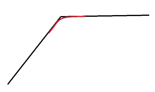
Instead of going along the black line as gcode instructs. It might be better to go along the red line. It will not only result in smoother motion, it might actually produce a better representation of the actual gcode path due to inertia of the print head. So basicly it's like a "pressure advance" for the XY motion. -
Is it not what CNC do?
-
@shen
I would avoid even to suggest such a behavior unless it is made optional. The image actually depicts a corner replaced by an arc. This is a decision to be made when generating the GCode for a job (3D printing or milling) and not to be done by the controller in the machine. Just imagine items with sharp edges that must mate properly. With the suggested path that might no longer happen.If the path smoothing is desired because of the STL 3D models, why not look for a slicer that supports arc fitting and generates G2/G3 commands? Why not looking for a GCode processor that reads the file produced by the slicer and changes it to G2/G3 commands where possible? In the end the controller should do exactly what it is instructed to do.
As a side note, it might be more interesting to do a side-by-side comparison between Duet and some board that supports a firmware with higher order motion planning. Is there any difference? Is it really worth the effort?
-
In a world with inertia, no controller can do exactly what it is instructed to do, at anything above the very lowest cutting speeds. This truth has been accepted in the CNC world for decades, because the gantry of a CNC may weigh many kilos. Going all the way back to proprietary controllers, and MACH in all its incarnations, several of the many tuning parameters traded "accuracy to g-code" vs. "speed".
Path accuracy vs. speed is part of "tuning a machine to its controller" during initial setup, AND tuning individual cuts for repetitive production runs.
3D printing seems to have avoided the nuances of this, through a combination of lighter gantries and not caring as much about the actual path. Sorry, but it is true. The "ringing" that is currently considered acceptable after turning a corner in most 3D prints is absolutely intolerable in the CNC world. I realize there are printers that have no visible ringing... but, current state of the art, they are the exception, not the rule.
Having said all of that, I don't really want to steer the debate down a bunch of anecdotal judgement calls of what is acceptable or not.
Instead, let me convey a data point:
I have several CNC rigs. One of them is a router, with 24" (600mm) by 60" (1500mm close enough) cut area. Uses Nema25s at 70v driven by "Gecko" drivers and a honking big 'toroidal' transformer based power supply. Tons of muscle.
I've used it to cut many things in "repetitive production". That is tens to dozens of repeats out of a sheet of material. Tens to dozens of sheets to produce hundreds of parts. Mostly cutting FR4 (think circuit board material, without the copper). Difficult stuff to cut accurately, due to the fibers inside.
This machine started with a MACH3 controller and a "parallel port" break out board driven by a "smoothstepper" board. Tuning for "looks like" the desired path, and note, NOT "exactly like"... just visually close enough to see no defects, tuning for that vs. tuning for "a tiny bit of visual oddity where a direction change occurs" makes HOURS of difference in a full sheet cut (faster). Hours.
Later changed that same machine to a TinyG, specifically for the "Constant Jerk" motion algorithm. Shaved tons of time off of many cuts.
There are so many variables in any cut it is very hard to give a factual comparison... what I can tell you is how it changed rapids (fast moves while not cutting). With Mach, the fastest rapids that did not cause mechanical issues were about 90 to 100 inches per second. With TinyG on the exact same mechanics, rapids of 300 IPS became normal, and really much smoother.
By the way, TinyG has several known flaws, and its developers have moved on to G2, and these flaws have not been fixed in the last couple of years. I find it worthwhile to work around these, simple because of the goodness of the constant jerk.
Summary: My hands on experience with larger heavier machines (than most 3D printers), and with Mach3 vs. TinyG, tells me that Constant Jerk is VERY VERY VERY VERY VERY worth pursuing.
Perhaps my experiences do not apply... nonetheless, a long post with a hard data point or two for people to mull over.
-
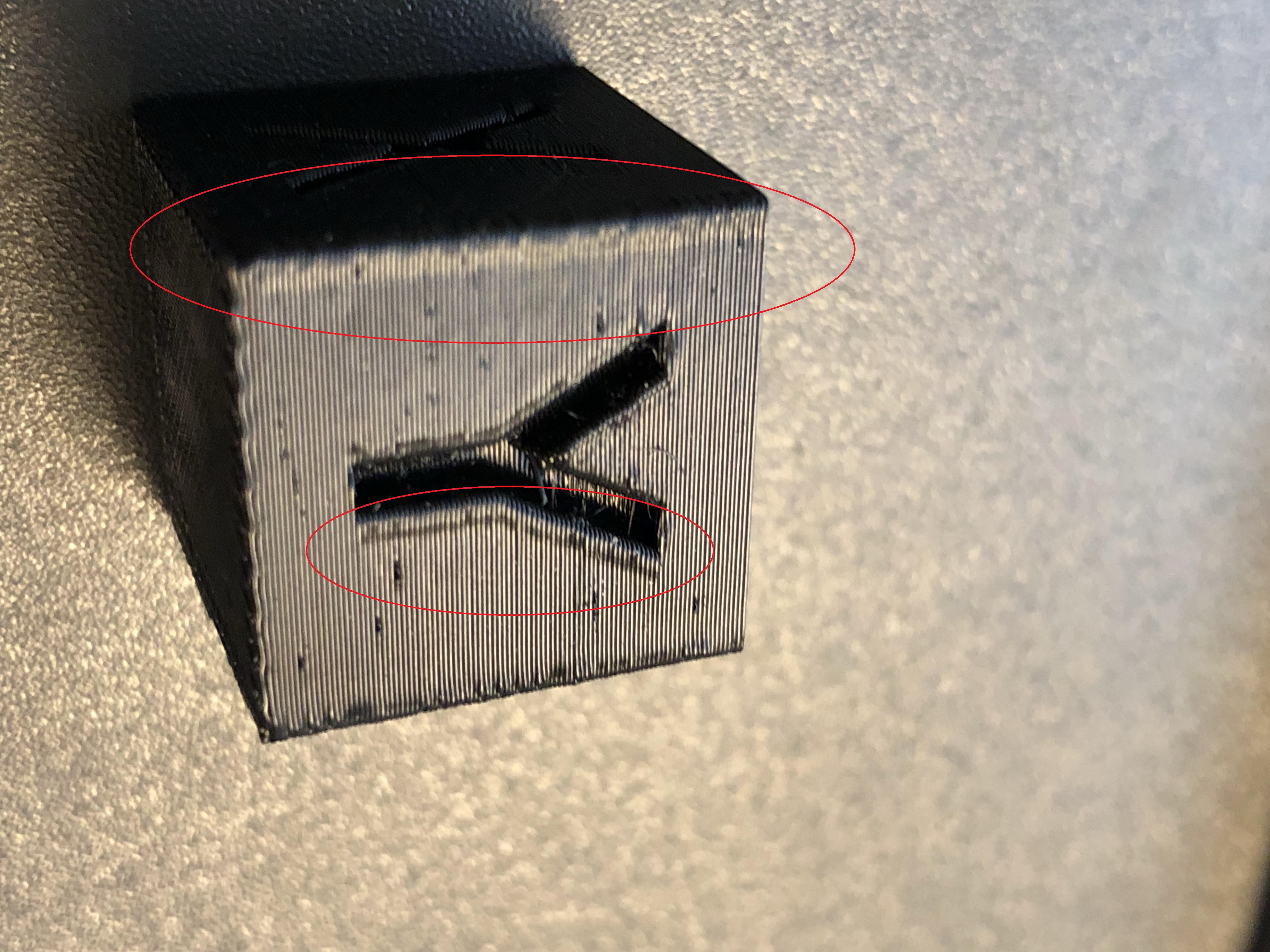
First of all the graph is exaggerated. In practice it would be a much smaller amount. When you make a corner at a high speed, the nozzle would go over the instructed position, as in the picture below.

It compensate for that. Also I would imaging this work the similar to pressure advance, it would have a constant k to decide the amount of compensation, and the compensation is proportional to the acceleration the nozzle experiences. So when you print at slow speed, or when the cornering angle is small, the acceleration/deceleration would be small, which results in less compensation.Also I can't agree with you that the controller should do exactly what the gcode instructed it to do. I my opinion, gcode is the theoretical motion path and speed, but in reality you have acceleration/jerk/pressure advance to try to compensate for physical effects and generate the best representation of the gcode.
-
If such feature can be activated/deactivated with G-Codes, slicers could choose to let the firmware correct paths or not, depending on its needs.
-
A controller CANNOT "Do what the gcode says". Gcode says "move along path to point x,y at feedrate f", and the next gcode says "now, point x2y2". This involves "turning a corner". Changing the mechanics to that path CANNOT happen at feedrate f.
The planner must accelerate, decelerate, etc. The amount that it does so is ALWAYS a compromise.
That compromise can be planned in dozens of ways. Sixth order is one of those many ways.
"Turn it on or off"? What you really mean is "Select this planning/accel/jerk algorithm over that one". Don't think for a second that the one currently embodied in any given firmware is perfect.
-
I know, but as you say, it is compromises. So, if one could choose one or the other, it is better. For example, reduce ringing but rounded corners, or sharp corners but ringing... Just an idea...
-
There seems to be a misinterpretation of the graphs shown in the page explaining higher order motion planning. Those have nothing to do with automatically replacing corners with arcs, on the contrary. With higher order motion planning the controllers try to reduce the motion related artifacts (missed steps, ringing etc.) as much as possible, while also indirectly reducing other problems (like cutting tool bending, especially on straights as the tool goes slow enough to bend less when getting close to the final position).
I don't have Danal's experience (never really used any large CNC or one with a gantry exceeding 15kg), but I still consider that purposely replacing corners with arcs is not good, at least now without the possibility of disabling it! My message was mostly about "path smoothing".
Another thing that the 3D printing world knows nothing about is the two separate passes when milling - roughing and finishing. Corners rounding might be OK when roughing with some left over material for the finishing pass, but most CAM tools used for milling already do that.
Now on the Mach3 vs TinyG comparison, I can't comment on that matter. But it would be interested to know overall results when using TinyG with and without "constant jerk" algorithm (if there is a way to disable it!). There might be many more differences making TinyG better than Mach3 for your specific situation. I have first hand experience with GRBL vs Duet. I have found out that G2/G3 should be limited on my current setup to 2100mm/min with Duet while with GRBL I can go up to 2500mm/min (maximum mechanically possible). If beyond 2100mm/min (like 2140mm/min, so just 2% faster) the machine sounds like breaking into pieces when executing some of the G2/G3 commands. Overall Duet is much better, but for this particular task GRBL beats it, for now! That is why I consider that pure Mach3 vs TinyG comparison is not correct as we are discussing motion planning algorithms, so we should rely more on comparisons done on the same controller.
-
The rounding of corners I proposed is on a very small scale just to counter the effect of flexibility and inertia. The distance nozzle overshoot on a 90 degree corners is usually between 0.05 to 0.1mm. So I won't only add a arc with that radius to just counter the overshoot, and while it does that it also proves a smoother motion. And the rounding compensation should be proportional to the acceleration experienced by the nozzle, so when you draw perimeter with a slower speed, the amount of compensation would be less.
-
Catalin_RO,
I completely agree that there are many more differences between MACH and TinyG than just the philosophy behind the motion algorithm.
At the same time... watch this video:
https://www.youtube.com/watch?v=Uq1Hawd6ONE&feature=youtu.be&t=6
Nothing special is being done to bring the weight to a stop at the end of each cycle... except "constant jerk".