Homed Height
-
Hi,
this is my config.g (Duet3D wiffi + Smart effector):
; Configuration file for Duet WiFi (firmware version 1.20 or newer)
; executed by the firmware on start-up
;
; generated by RepRapFirmware Configuration Tool on Fri Apr 20 2018 11:48:27 GMT+0200 (W. Europe Summer Time); General preferences
G90 ; Send absolute coordinates...
M83 ; ...but relative extruder moves
M555 P1 ; Set firmware compatibility to look like RepRapFirmare
M665 R190 L375 B85 H600 ; Set delta radius, diagonal rod length, printable radius and homed height
M666 X0 Y0 Z0 ; Put your endstop adjustments here, or let auto calibration find them; Drives
M569 P0 S0 ; Drive 0 goes forwards
M569 P1 S0 ; Drive 1 goes forwards
M569 P2 S1 ; Drive 2 goes forwards
M569 P3 S1 ; Drive 3 goes forwards
M350 X16 Y16 Z16 E16 I1 ; Configure microstepping with interpolation
M92 X80 Y80 Z80 E663 ; Set steps per mm
M566 X2400 Y2400 Z2400 E1200 ; Set maximum instantaneous speed changes (mm/min)
M203 X36000 Y36000 Z36000 E1200 ; Set maximum speeds (mm/min)
M201 X1000 Y1000 Z1000 E1000 ; Set accelerations (mm/s^2)
M906 X1200 Y1200 Z1200 E700 I60 ; Set motor currents (mA) and motor idle factor in per cent
M84 S15 ; Set idle timeout; Axis Limits
M208 Z0 S1 ; Set minimum Z; Endstops
M574 X2 Y2 Z2 S1 ; Set active high endstops; Z-Probe
M558 P5 R0.4 H5 F120 T6000 ; Set Z probe type to effector and the dive height + speeds
G31 P100 X0 Y0 Z-0.1 ; Set Z probe trigger value, offset and trigger height
M557 R85 S20 ; Define mesh grid; Heaters
M305 P0 T100000 B4138 C0 R4700 ; Set thermistor + ADC parameters for heater 0
M143 H0 S100 ; Set temperature limit for heater 0 to 100C
M305 P1 X200 ; Configure thermocouple for heater 1
M143 H1 S330 ; Set temperature limit for heater 1 to 330C; Fans
M106 P0 S0.3 I0 F500 H-1 ; Set fan 0 value, PWM signal inversion and frequency. Thermostatic control is turned off
M106 P1 S1 I0 F500 H1 T40 ; Set fan 1 value, PWM signal inversion and frequency. Thermostatic control is turned on
M106 P2 S1 I0 F500 H1 T40 ; Set fan 2 value, PWM signal inversion and frequency. Thermostatic control is turned on; Tools
M563 P0 D H1 ; Define tool 0
G10 P0 X0 Y0 Z0 ; Set tool 0 axis offsets
G10 P0 R0 S0 ; Set initial tool 0 active and standby temperatures to 0C; Automatic saving after power loss is not enabled
; Custom settings are not configured
I'm trying to go down and see with M114 the value....increment value H on M665 ....homing all axis and try again...
but the value seems to be more than the expected....now is 600 and when I go down...at 0 there is space...
I measured the distance between the hotend and the bed....and is less the 600mm....and I don't now how to fix this...
I never used autocalibration ( why? ..because I thought that before to do that...I need to fix the height....I'm wrong? because I'm thinking that if the height is not correct....when autocalibration start...can touch the bed with more force then needed and break the glass )
what can I do?
Thx
Giulio
-
I think of my misunderstanding about absolute/relative positioning
-
I found a value that seems to works.
Now I followed this:
Measuring the trigger height
The Z probe trigger height must not vary significantly with XY position. Measure the trigger height of your Z probe at various XY positions and make sure it is consistent. To measure the trigger height:
- Make sure there is no filament stuck to the nozzle (you may want to do this test with the nozzle hot)
- Cancel any existing bed compensation by sending M561
- Send M208 S1 Z-3 to temporarily allow Z moves down to Z=-3mm. This is to ensure that you can lower the nozzle all the way to the bed in step 5.
- Command the print head to the XY coordinates you want to probe
- Command the print head down in small steps until the nozzle just touches the bed or just grips a sheet of paper. You may need to send M564 S0 to allow movement lower than where the firmware thinks Z=0 is. You may also wish to create a macro to lower the head by e.g. 0.02mm to get greater accuracy (G91 followed by G1 Z-0.02).
- Send G92 Z0 to define that height as Z=0
- Command the nozzle up 5mm (G1 Z5)
- Send G30 S-1 to probe the bed without resetting the Z=0 position
- Read off the Z height from the web interface. That is the trigger height.
- Repeat the previous two steps a couple of times to make sure you are getting a consistent result
- Repeat steps 4-10 for the other XY positions you want to check
When you have established what the trigger height is, set the Z parameter og the G31 command in config.g to that value.
and found Z-probe height -0.37 and I decided to run an auto delta calibration.
this is the step of autocalibration:
G30 P0 X0 Y84.9 H0 Z-99999
G30 P1 X49.9 Y68.69 H0 Z-99999
G30 P2 X80.74 Y26.24 H0 Z-99999
G30 P3 X80.74 Y-26.24 H0 Z-99999
G30 P4 X49.9 Y-68.69 H0 Z-99999
G30 P5 X0 Y-84.9 H0 Z-99999
G30 P6 X-49.9 Y-68.69 H0 Z-99999
G30 P7 X-80.74 Y-26.24 H0 Z-99999
G30 P8 X-80.74 Y26.24 H0 Z-99999
G30 P9 X-49.9 Y68.69 H0 Z-99999
G30 P10 X0 Y42.4 H0 Z-99999
G30 P11 X36.72 Y21.2 H0 Z-99999
G30 P12 X36.72 Y-21.2 H0 Z-99999
G30 P13 X0 Y-42.4 H0 Z-99999
G30 P14 X-36.72 Y-21.2 H0 Z-99999
G30 P15 X-36.72 Y21.2 H0 Z-99999
G30 P16 X0 Y0 H0 Z-99999 S3the steps in bold are steps where nothing triggered...and...this is the result:
Error: Compensation or calibration cancelled due to probing errors
-
I need to adjust only H parameter on the steps where the probe not triggered and run autocalibration again or I'm following a wrong way?
-
corrected some values and autocalibration terminated correctly with this result:
Calibrated 3 factors using 17 points, deviation before 2.173 after 2.069
-
-
You should not need to use any H parameters on the G30 commands in bed.g when using the Smart Effector, or any other nozzle contact bed probe.
-
When running auto calibration for the first time, increase the M558 H parameter as recommended in the wiki page on delta calibration.
-
If your homed height has come out at 600mm but is in reality less than this, perhaps you have the wrong steps/mm set in config.g? 80 steps/mm is correct for 1.8deg motors used with 20-tooth GT pulleys.
-
You should calibrate at least 4 parameters (not 3) and preferably 6.
-
-
ok ..my step motors are 0.9 ...I think I should double the value and use 160
-
@bulka said in Homed Height:
ok ..my step motors are 0.9 ...I think I should double the value and use 160
Yes, if you are using 20-tooth pulleys. If your pulleys are 16-tooth then it should be 200.
-
yes is a pulley 20T. thx
")
I corrected the config file and now the H is what I measured:
; General preferences
G90 ; Send absolute coordinates...
M83 ; ...but relative extruder moves
M555 P1 ; Set firmware compatibility to look like RepRapFirmare
M665 R55.41 L355.00 H366.75 B170.00
M666 X0 Y0 Z0; Drives
M569 P0 S0 ; Drive 0 goes forwards
M569 P1 S0 ; Drive 1 goes forwards
M569 P2 S1 ; Drive 2 goes forwards
M569 P3 S1 ; Drive 3 goes forwards
M350 X16 Y16 Z16 E16 I1 ; Configure microstepping with interpolation
M92 X160 Y160 Z160 E663 ; Set steps per mm
M566 X2400 Y2400 Z2400 E1200 ; Set maximum instantaneous speed changes (mm/min)
M203 X36000 Y36000 Z36000 E1200 ; Set maximum speeds (mm/min)
M201 X1000 Y1000 Z1000 E1000 ; Set accelerations (mm/s^2)
M906 X1200 Y1200 Z1200 E700 I60 ; Set motor currents (mA) and motor idle factor in per cent
M84 S15 ; Set idle timeout; Axis Limits
M208 Z0 S1 ; Set minimum Z; Endstops
M574 X2 Y2 Z2 S1 ; Set active high endstops; Z-Probe
M558 P5 R0.4 H5 F120 T6000 ; Set Z probe type to effector and the dive height + speeds
G31 P100 X0 Y0 Z-0.252 ; Set Z probe trigger value, offset and trigger height
M557 R85 S20 ; Define mesh grid; Heaters
M305 P0 T100000 B4138 C0 R4700 ; Set thermistor + ADC parameters for heater 0
M143 H0 S100 ; Set temperature limit for heater 0 to 100C
M305 P1 X200 ; Configure thermocouple for heater 1
M143 H1 S330 ; Set temperature limit for heater 1 to 330C; Fans
M106 P0 S0.3 I0 F500 H-1 ; Set fan 0 value, PWM signal inversion and frequency. Thermostatic control is turned off
M106 P1 S1 I0 F500 H1 T40 ; Set fan 1 value, PWM signal inversion and frequency. Thermostatic control is turned on
M106 P2 S1 I0 F500 H1 T40 ; Set fan 2 value, PWM signal inversion and frequency. Thermostatic control is turned on; Tools
M563 P0 D H1 ; Define tool 0
G10 P0 X0 Y0 Z0 ; Set tool 0 axis offsets
G10 P0 R0 S0 ; Set initial tool 0 active and standby temperatures to 0C -
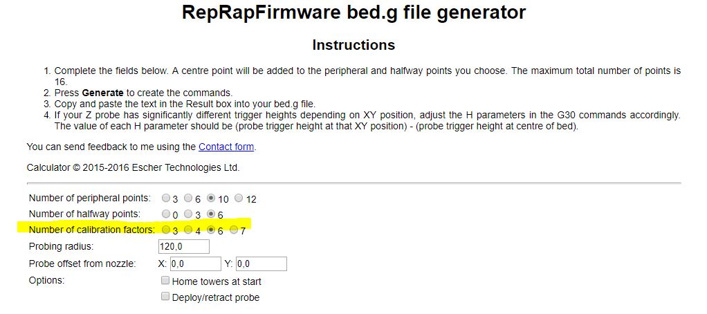
I changed the calibration on bed config file using :http://www.escher3d.com/pages/wizards/wizardbed.php
-
@bulka said in Homed Height:
M665 R55.41 L355.00 H366.75 B170.00
what I'm not sure about this command ... the parameter R and L ( don't kill me )
I don't understood perfectly how to calculate it...

I changed the M558 as suggested in the wiki ( and by you ) to M558 P5 R0.4 H20 F120 T6000
-
@bulka said in Homed Height:
@bulka said in Homed Height:
M665 R55.41 L355.00 H366.75 B170.00
what I'm not sure about this command ... the parameter R and L ( don't kill me )
I don't understood perfectly how to calculate it...
I changed the M558 as suggested in the wiki ( and by you ) to M558 P5 R0.4 H20 F120 T6000
L is the rod length measured between bearing centres. If you are using Haydn Huntley's magnetic rods, each rod carries a label on which its length is written, so use that figure.
R is the delta radius. The exact value will be found by calibration, so you need to provide only an approximate value. Use the horizontal distance subtended by any rod, measured between bearing centres, when the effector is central.
-
ok.
changed to:
M665 R168 L360 H366.75 B170.00
M666 X0 Y0 Z0I'll try to start auto calibration
-
Calibrated 6 factors using 16 points, deviation before 1.322 after 0.029
-
change calibration to 7 factor:
Calibrated 7 factors using 16 points, deviation before 1.201 after 0.016
-
@bulka not wise to use 7 factor if you know your rod length properly use either 6 or 8
-
ok, I read after your answer on wiki: " typical delta printer builds, 6-factor is best"
Changed beg config file:

13:21:29
Calibrated 6 factors using 16 points, deviation before 0.017 after 0.01413:23:13
M665
Diagonal 363.663, delta radius 173.193, homed height 366.386, bed radius 170.0, X -0.034°, Y -0.209°, Z 0.000°13:23:09
M666
Endstop adjustments X0.20 Y0.83 Z-1.03, tilt X0.00% Y0.00%If I'm not wrong...after calibration....the Diagonal was changed....it's wrong to use 6 factors using 16 points?
-
@bulka the drag rod length was changed by the previous 7 factor cal you need to manually reset the rod length and run it again with either 6 or 8 factor cal
-
done
thank youthank you DC