Beginner Needs Help - Anycubic Kossel Plus + Duet WiFi -- HOW?
-
@dc42 said in Beginner Needs Help - Anycubic Kossel Plus + Duet WiFi -- HOW?:
I think you mean G32 not G31. See https://duet3d.dozuki.com/Wiki/Calibrating_a_delta_printer#Section_Saving_the_calibration_results.@dc42 - Actually, I got the G31 from your instructions a few entries above. See:
@dc42 said in Beginner Needs Help - Anycubic Kossel Plus + Duet WiFi -- HOW?:
You can do manual configuration as long as you are running fairly recent firmware. Set Z probe type 0 (that's P0 in the M558 command in config.g) to tell the firmware that you have no Z probe. Then run G31 as usual. The web interface will prompt you.
So what would be the best way to do a manual calibration with P0 in the M558 command?
-
@mindbender9 said in Beginner Needs Help - Anycubic Kossel Plus + Duet WiFi -- HOW?:
@dc42 - If you design both the Duet board and the IR Sensor, why didn't you make the connector a 4-pin connector by default (to match the Duet's 4-pin Z-probe connector)? Just wondering, because I have to decide whether to splice a 4-pin connector end to the IR Sensor probe.
There isn't room on the IR sensor PCB to fit a Molex connector. Also the IR sensor doesn't only work with the Duet.
@dc42 said in Beginner Needs Help - Anycubic Kossel Plus + Duet WiFi -- HOW?:
My mistake, I meant G32.
-
So here's what's happening, as of Monday night:
-
Still can't print. The nozzle remains roughly 5-10cm off the bed, so it literally dumps filament onto the bed and let's it pile up. It doesn't look like the nozzle moves vertically as the printing progresses, so it ends up pushing the print around the bed. The PLA remains soft and mushy.
-
Cannot auto-calibrate. I need the IR Sensor to be mounted, and it's not mounted because I can't print a mount. Sounds like a Catch-22.
-
Manual calibration doesn't seem to help, because I can do the 2-paper test and printing is still screwy. Nothing changes.
Any suggestions? Anything?
-
-
You can "auto calibrate" manually as I tried to explain in my earlier reply. See https://duet3d.dozuki.com/Wiki/Calibrating_a_delta_printer. The online configurator can generate the bed.g file for you.
-
@mindbender9 said in Beginner Needs Help - Anycubic Kossel Plus + Duet WiFi -- HOW?:
- Still can't print. The nozzle remains roughly 5-10cm off the bed, so it literally dumps filament onto the bed and let's it pile up. It doesn't look like the nozzle moves vertically as the printing progresses, so it ends up pushing the print around the bed. The PLA remains soft and mushy.
This is an expected result if calibration has not been performed properly.
- Cannot auto-calibrate. I need the IR Sensor to be mounted, and it's not mounted because I can't print a mount. Sounds like a Catch-22.
Would recommend either sending me an STL to print for you, or sending STL to Shapeways.
- Manual calibration doesn't seem to help, because I can do the 2-paper test and printing is still screwy. Nothing changes.
A video of the manual calibration being performed would be helpful, so we can spot anything being done incorrectly.
I'd also recommend checking that the IR sensor is working properly, so you don't become frustrated when you get the mount in. Wire it up per the instructions and check that the LED illuminates when you hold a piece of paper in front of it, and also check that the z-probe value in Duet Web Control changes accordingly.
-
To get the very first prints, perform manual probing. This is a pain... be meticulous and patient...
-
M558 must have P0. This says there is no probe. Reboot after changing this.
-
Issue a G32 (or use the web "Auto Delta Calibration")
-
This pop up will appear in the web interface:
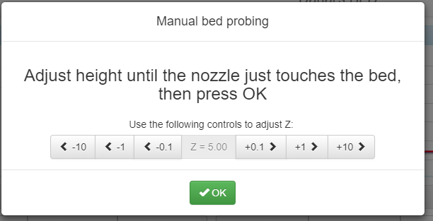
Use the controls to adjust until a business card "drags" between the nozzle and the plate. Then click OK.
Repeat for each point.
- When complete, do an M500 to save. (Be sure there is an M501 near the end of your config.g to load)
.
.
Just for fun, you may want to do a M665 before and after, to see what changed. -
-
Thank you for the tips. I will attempt to manually calibrate before testing the IR sensor. I appreciate your help. Thanks again.
-
Thank you for your steps. I performed two of the manual probes and received the following results when typing M665:
Attempt #1:
M665
Diagonal 271.000, delta radius 134.000, homed height 745.351, bed radius 85.0, X 0.000°, Y 0.000°, Z 0.000°A print attempt resulted in the nozzle positioning itself from the top of the printer (near "home") and dripping filament until I halted the print.
Attempt #2 Results:
M120
G91
G1 Z-10 F6000
M121
Calibrated 3 factors using 4 points, deviation before 286.144 after 1.67M665
Diagonal 271.000, delta radius 134.000, homed height 459.464, bed radius 85.0, X 0.000°, Y 0.000°, Z 0.000°I don't understand why the "homed height" values are so large.
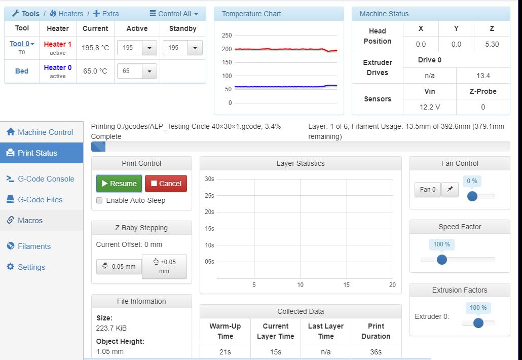
The second attempt to print after another calibration resulted in the same print from the top of the printer. I halted this print as well - here is a screenshot of the web interface at the time:

Any idea why these manual calibrations are resulting in prints from the top of the printer? What did I miss?
-
@dc42 - Thank you for replying. I appreciate your help.
@dc42 said in Beginner Needs Help - Anycubic Kossel Plus + Duet WiFi -- HOW?:
You can "auto calibrate" manually as I tried to explain in my earlier reply.I completed two manual calibrations (M558 P0 X0 Y0 Z1 H5 F1000 T5000 I1) and had very odd results. The nozzle attempted to print from tall heights.
See https://duet3d.dozuki.com/Wiki/Calibrating_a_delta_printer. The online configurator can generate the bed.g file for you.
-
I have to admit that I have a difficult time following the Duet wiki. Although American English is my only language, the wiki comes across as engineer's notes rather than howto instructions. I realize that a failure to understand is my problem, but I can't grasp what I'm supposed to do. Still trying, though.
-
I used the Online Configurator to recreate the bed.g file:
; generated by RepRapFirmware Configuration Tool on Sun May 13 2018 19:16:40
M561 ; clear any bed transform
G31 X0 Y0 ; don't want any probe offset for this - ADDED 5/21/2018G28 ; home the printer
M401 ; deploy the Z probeG30 P0 X0.00 Y85.00 Z-99999 H0
G30 P1 X73.61 Y-42.50 Z-99999 H0
G30 P2 X-73.61 Y-42.50 Z-99999 H0
G30 P3 X0 Y0 Z-99999 S3M402 ; retract the Z probe
G1 X0 Y0 Z150 F15000 ; get the head out of the way of the bed
Thanks again for the help.
-
-
try generating a new bed.g file using DC42 Bed file generator use at least 10 points and select 6 factor (or even change the s6 in the generated output to S8)
also rather than use m500 to store the values in eprom I would run the routine at least twice then send M665 and M666 and graft the resultant figures into your Config.g. I learnt a long time ago that useing the EEPTOM type setting can lead you seriously astray when something changes for example if you change something in your config.g and that part is also in the config-override then the override will take priority when you run M501 to retrieve it. Can leave you scratching your head.
You could of course still use M500 to save the results and then cut and paste the two lines back to your Config.g and then delete the override file to save you falling into that trap.
HTH
Doug
-
@mindbender9 said in Beginner Needs Help - Anycubic Kossel Plus + Duet WiFi -- HOW?:
I don't understand why the "homed height" values are so large.
Are you sure that you have the correct X, Y and Z steps/mm set in config.g? The common values for a delta printer with GT2 belts are:
1.8deg motors, 20 tooth pulley: 80 steps/mm
1.8deg motors, 16 tooth pulley: 100 steps/mm
0,9deg motors, 20 tooth pulley: 160 steps/mm
0.9deg motors, 16 tooth pulley: 200 steps/mm -
Hi @dc42.
I believe these are 1.8 deg motors. But I apologize, I don't know what a tooth pulley is or where it's located on the printer.
Trying to google-fu the part, but not seeing it.
-
The pulleys I am referring to are on the stepper motor shafts. Each one will have 16 or 20 teeth on it - or just possibly 18.
You can check that the steps/mm is correct. Home the printer, then send G91 followed by G1 Z-100. The effector should move down 100mm. If it moves some other distance, you have incorrect steps/mm set in config.g.
-
@mindbender9 in your first post, it shows your config.g contains
M92 X80 Y80 Z80 E663 ; Set steps per mmDouble check that this has not changed, because I believe this is probably correct.I have an Anycubic Kossel Linear (NOT plus) and it has 1.8 motors and 20 tooth pulleys, resulting in 80 steps per mm. 80 per mm works correctly in the Marlin/Trigorilla native printer (along with a 16 microstep setting).
As an aside, your steps/mm for your extruder look odd to me. My Anycubic is set to 96. Please note this is NOT your problem with movement/homing/probing... and you can check this later... just mentioning it because we are looking at M92.
As David said, be sure and home, then command a 100mm move and measure the results, just to be sure.
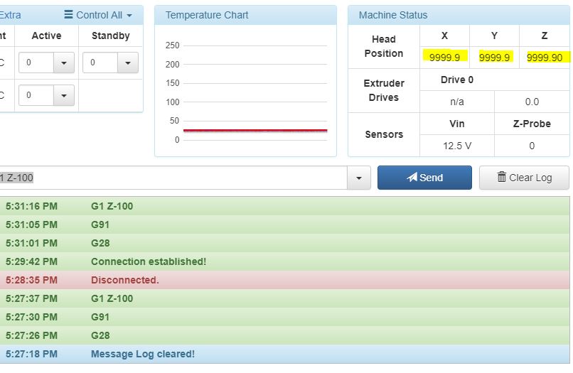
G28 G91 G1 Z-100 -
When I enter G28, the printer arms rise to the top and stop. G91 does nothing.
When I enter G1 Z-100, nothing happens and the arms remain in place at the top of the printer. No errors are registered in the G-code Console.
One interesting thing is the "Head Position" for all three axis are set at "9999.9" after homing. Would this be related?

Here's my config.g for reference:
; Configuration file for Duet WiFi (firmware version 1.20 or newer)
; executed by the firmware on start-up
;
; generated by RepRapFirmware Configuration Tool on Sun May 13 2018 19:16:40 GMT-1000 (Hawaiian Standard Time); General preferences
G90 ; Send absolute coordinates...
M83 ; ...but relative extruder moves
M555 P1 ; Set firmware compatibility to look like RepRapFirmare;*** The homed height is deliberately set too high in the following - you will adjust it during calibration.
M665 R134 L271 B85 H285 ; Set delta radius, diagonal rod length, printable radius and homed height
M666 X0 Y0 Z0 ; Put your endstop adjustments here, or let auto calibration find them; Network
M550 Pduettest
M552 S1 ; Enable network
M586 P0 S1 ; Enable HTTP
M586 P1 S0 ; Disable FTP
M586 P2 S0 ; Disable Telnet; Z-Probe
M558 P0 X0 Y0 Z1 H5 F1000 T5000 I1 ; Set Z probe type to MANUAL and the dive height + speeds
G31 X0 Y0 Z0 P100 ; Set Z probe trigger value, offset and trigger heightM557 R130 S20 ; Define mesh grid
; Drives
M569 P0 S1 ; Drive 0 goes forwards
M569 P1 S1 ; Drive 1 goes forwards
M569 P2 S1 ; Drive 2 goes forwards
M569 P3 S1 ; Drive 3 goes forwards
M350 X16 Y16 Z16 E16 I1 ; Configure microstepping with interpolation
M92 X80 Y80 Z80 E663 ; Set steps per mm
M566 X1200 Y1200 Z1200 E1200 ; Set maximum instantaneous speed changes (mm/min)
M203 X18000 Y18000 Z18000 E1200 ; Set maximum speeds (mm/min)
M201 X1000 Y1000 Z1000 E1000 ; Set accelerations (mm/s^2)
M906 X1000 Y1000 Z1000 E800 I30 ; Set motor currents (mA) and motor idle factor in per cent
M84 S30 ; Set idle timeout; Axis Limits
M208 Z0 S1 ; Set minimum Z; Endstops
M574 X2 Y2 Z2 S1 ; Set active high endstops; Heaters
M305 P0 T100000 B4267 C0 R4700 ; Set thermistor + ADC parameters for heater 0
M143 H0 S120 ; Set temperature limit for heater 0 to 120C
M305 P1 T100000 B4267 C0 R4700 ; Set thermistor + ADC parameters for heater 1
M143 H1 S275 ; Set temperature limit for heater 1 to 275C; Fans
M106 P0 S0.3 I0 F500 H-1 ; Set fan 0 value, PWM signal inversion and frequency. Thermostatic control is turned off
M106 P1 S1 I0 F500 H1 T45 ; Set fan 1 value, PWM signal inversion and frequency. Thermostatic control is turned on
M106 P2 S1 I0 F500 H1 T45 ; Set fan 2 value, PWM signal inversion and frequency. Thermostatic control is turned on; Tools
M563 P0 D0 H1 ; Define tool 0
G10 P0 X0 Y0 Z0 ; Set tool 0 axis offsets
G10 P0 R0 S0 ; Set initial tool 0 active and standby temperatures to 0C; Automatic saving after power loss is not enabled
M501
; Custom settings are not configured -
I have to ask: Is there a particular order or hierarchy for G-codes in the configuration files? Could that be a cause for the weird results/actions?
-
@mindbender9 said in Beginner Needs Help - Anycubic Kossel Plus + Duet WiFi -- HOW?:
One interesting thing is the "Head Position" for all three axis are set at "9999.9" after homing. Would this be related?
Yes! it means that the parameters in your M665 and M666 commands are mechanically impossible. What M665 and M665 commands do you currently have in config.g? Check that they are not being overridden by other commands in config-override.g.
-
Hi @dc42
My config.g has the following values for M665 and M666:
M665 R134 L271 B85 H285 M666 X0 Y0 Z0 My config-override.g file (which I had no idea existed) has the following values:
; This is a system-generated file - do not edit ; Delta parameters M665 L271.000 R134.000 H1032.754 B85.0 X0.000 Y0.000 Z0.000 M666 X250.573 Y79.532 Z-330.105 A0.00 B0.00 ; Heater model parameters M307 H0 A90.0 C700.0 D10.0 S1.00 V0.0 B1 M307 H1 A340.0 C140.0 D5.5 S1.00 V0.0 B0 M307 H2 A340.0 C140.0 D5.5 S1.00 V0.0 B0 M307 H3 A340.0 C140.0 D5.5 S1.00 V0.0 B0 M307 H4 A340.0 C140.0 D5.5 S1.00 V0.0 B0 M307 H5 A340.0 C140.0 D5.5 S1.00 V0.0 B0 M307 H6 A340.0 C140.0 D5.5 S1.00 V0.0 B0 M307 H7 A340.0 C140.0 D5.5 S1.00 V0.0 B0 I’m guessing that those wild numbers in the config-override.g file should not be there? Should their M665 and M666 values match the config.g G-code values?
-
The values in config-override.g were written when you ran M500 after auto calibrating. I suggest you delete them and restart the Duet. When you have auto calibration working well and you no longer have those 9999.9 values for the axis positions, you can run M500 to save the new values to config-override.g.
It is the M666 values in config-override.g that are causing the problem.
-
With your advice, I did a manual 6 point calibration using the paper test. I'm now able to do a test print of a 1-layer circle, but it's really ragged and rough. It's not pretty, but it's my first print and I'm psyched!

I'll have to figure out how to clean this up and fine-tune it a little more before printing the IR sensor bracket (my first real 3D printing project).
With all honesty, you and the forum contributors made it possible for me to get this far. Thank you very much for this breakthrough, David/@dc42.
This is a great start, and I appreciate everyone's help!