Non-Linear Extrusion
-
Any guides for setting this up? Can we force it to be applied for extrusion only for testing? When extruder steps are set for an accurate 50mm @ a feed rate of 82mm/min (30mm/s @0.2mm layer, 0.55 track width, and 1.75mm filament) if I request 100mm @F440 (160mm/sec) I get a 12.5mm shortfall. Retracts and advances are typically F3000 so expect these effectively loose position on each action, hence the need for the additional (sometimes negative) unretract?
-
There's an error in my maths! Changed the wrong bit of my formular which would have exagerated the problem if it didn't invent it! I'll be doing three runs at the equivilant of 30, 50, 70, 90, 110, 130, 150, and 170mm/s and plotting the results.I'm still interested in a guide but ignore my numbers for the minute!
Edit: No error as it happens... My formula for getting the feed rate was:
(0.2 * 0.55 * 80 * 60)/(pi * ((1.75/2) ** 2)) which is:
([layer] * [extrusion width] * [print speed mm/sec] * [seconds/min]) /
(pi * [filament radius] * [filament radius]) which in basic form is:[Target volume / min] / [cross sectional area of filament]
I'd started typing in my speed in place of the seconds/min, but I did it when the last calculation was 60mm/sec end result exactly the same...
-
I'm seeing the 'shark skin' surface effect when extruding fast and nice and shiney when extruding slow...
-
A graph as neat as this one is indeed a rare thing! The tested points where based on reaching the print speeds of 30, 50, 70, 90, 110, 130, 150, and 170mm/sec. I'll add a photo another time to show the shark skin effect, but in a nutshell the shiny on the extruded filament disappears at between 50 and 70mm/sec. As the extruder feed rate increases as does die swell - the extruded bead is thicker.
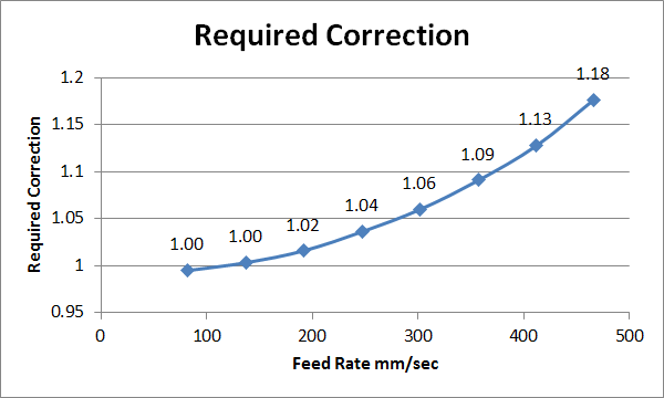
Edit: Given the first two data points I really should have had three decimal places on the labels, but you get the jist. My concern is will this graph still hold true when extruding real parts as there is extra resistance to the polymer coming out of the nozzle, particually if you are slightly over extruding. This would add back pressure which is the explanation for this effect on the gcode reference for non-linear extrusion correction....
Edit2: Dahm I'm buggy today. New graph coming with feed rate corrected and a few other tweaks...
")
-
I used the following to calibrate my extruder (I think @dc42 was the originator):
G28
G1 X0 Y0 Z100 F5000
M83
G1 E5 F600
M400
M291 S3 R"Extrusion test" P"Press OK to start test"

;G1 X50 F5000
G1 X50 E50 F60
M400
M291 S3 R"Measure extrusion" P"Measure filament taken at 1mm/sec extrusion, then press OK"

G1 X0 E50 F120
M400
M291 S3 R"Measure extrusion" P"Measure filament taken at 2mm/sec extrusion, then press OK"

G1 X50 E50 F180
M400
M291 S3 R"Measure extrusion" P"Measure filament taken at 3mm/sec extrusion, then press OK"

G1 X0 E50 F240
M400
M291 S3 R"Measure extrusion" P"Measure filament taken at 4mm/sec extrusion, then press OK"

G1 X50 E50 F300
M400
M291 S3 R"Measure extrusion" P"Measure filament taken at 5mm/sec extrusion, then press OK"

G1 X0 E50 F360
M400
M291 S3 R"Measure extrusion" P"Measure filament taken at 6mm/sec extrusion, then press OK"

G28
One one machine with a flex3drive extruder and an e3d v6 0.4 nozzle, testing PLA at 200deg, I ended up with M592 D0 A0.05 B0.003
-
Ok...
Changes:
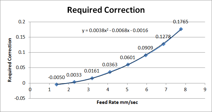
- Looks like the non linear correction gcode wants the A and B values to give the result interms of required correction - 1. Adjusted graph to suit.
- The gcode explanation is based on the filament speed in mm/sec. My axis title was right on the last graph, but not the plotted data which was just the F component of the G1 command.
- Added more decimals to the number.
- Got lazy and asked excel to add a second order polynomial trend line and give me the result.
Considering a polynomial in the form Bx^2 + Ax + C the ability to put the +c into the equation is missing from the gcode feature. I can only assume this is because I calibrated my extruder for a feedrate of around 2.5mm/sec extruder speed ish. Now onto the trial...
A & B for PETG 220C Titan, V6, 0.4 nozzle: A = -0.0068, B = 0.0038
-
@burtoogle Intersting to see the B value close to mine. Think the A value is may vary strongly depending on what speed you calculate your steps /mm for the extruder.
-
Just printed solid, 35 * 35 * 4mm, hatch only (45 degrees) test samples with print speeds running from 80 through to 180mm/sec. Typical weight around 5.82g with a min to max range that covered 0.06g! I make that about 0.25mm difference in input filament - assuming the filament was perfect! I've got varying quoted densities for the PETG. ON the supplier page it quotes 1.1 but I'm sure that's not accurate as that would make these samples over 100% dense, and they look under extruded. If the density is more like 1.2 then it's only a couple of percent under extruded which is a great result. Will aim to get the pressure advance dialled in tomorrow to sort out the densification towards the edges of the coupon - which could also be a thermal issue.
-
Mathematically inept person here. I get the principle behind M592 but, despite spending the last 2hrs reviewing vague G-Code documentation and a slew of forum posts, I still don't understand where these A and B values are coming from/how they are being calculated from the measurements you're taking. Can you help me, please?
-
There have been some longer posts in the past discussing this feature and how it came about. In a nutshell people had noticed that they needed a significant extrusion multiplier in order to achieve a specific density depsite having very carefully calculated and tested their extrusion steps per mm. What proved more challenging was that this correction changed depending on print speed. Essentially to continue to print accurately without non linear correction you'd have to calibrate your system to a specific volumetric output from the extruder and increase extrusion width if you wanted to print slower.
The graph that I plotted is the correction needed as the rate of volumetric output from the extruder increases. Extrusion speed is directly proportional to this rate because our nozzle diameter is constant - ignoring insignificant changes due to thermal expansion or wear.
In my case the output correction graph displays a quadratic, or second order polynomial equation. The A and B values are from the equation that best fits the graph and is fed back into the machine in order for it to correct for this predictable error in extrusion.
The standard quadratic is:
Ax^2 + Bx + C = yBecause this correction was initially implemented in the firmware to correct for a linear error the B and A have swapped around. There currently isn't a provision for the C value.
This is complicated by these values changing with extrusion temp and even more so with material change.
Edit: I'll try to find a good explanation for the maths side later.
-
A linear relationship is like speed and distance. If you go twice as fast you cover twice the distance in the same time. The equation would look like:
Speed * time = distance
If you plotted the distance travelled for a constant speed then the line would be straight - linear.
An example of a non linear relationship is the power a car needs to hold a certain speed. Roughly speaking due to air resistance when you double the speed the power require goes up by four. Four times the speed and the required power is sixteen times what it was at the lower speed. If you plotted that it would be a curve - non linear. The equation would get more complicated and be something like:
Fudge * Speed * Speed + other fudge * speed = power
...where fudge being something that accounts for how aerodynamic your car is and the other fudge allows for things that are directly related to speed such as rolling resistance of tyres.
That last equation is like what we have for the correction. In english it says that when you need twice the amount of polymer out of your extruder in the same amount of time you need to turn the extruder more than twice the distance, and the faster you extrude the larger the needed correction.
-
Can someone double check my math? Using this modified macro with M592 D0 A0 B0
Non-linear extrusion script from Duet forum. Used to adjust A and B parameters in M592.
;
G28
G1 X0 Y0 Z100 F5000
M83
G1 E5 F600
M400
M291 S3 R"Extrusion test" P"Press OK to start test"

G1 X100 E100 F60
M400
M291 S3 R"Measure extrusion" P"Measure filament taken at 1mm/sec extrusion, then press OK"

G1 X0 E100 F120
M400
M291 S3 R"Measure extrusion" P"Measure filament taken at 2mm/sec extrusion, then press OK"

G1 X100 E100 F180
M400
M291 S3 R"Measure extrusion" P"Measure filament taken at 3mm/sec extrusion, then press OK"

G1 X0 E100 F240
M400
M291 S3 R"Measure extrusion" P"Measure filament taken at 4mm/sec extrusion, then press OK"

G1 X100 E100 F300
M400
M291 S3 R"Measure extrusion" P"Measure filament taken at 5mm/sec extrusion, then press OK"

G1 X0 E100 F360
M400
M291 S3 R"Measure extrusion" P"Measure filament taken at 6mm/sec extrusion, then press OK"

G28
I get the following with PETG:
1mm/s = 98.9mm
2mm/s = 97.1mm
3mm/s = 94.5mm
4mm/s = 92mm
5mm/s = 88mm
6mm/s = 82mmSo I come up with
M592 D0 A-0.0593 B0.475Running the macro again:
1mm/s = aprox 118mm (went too far to measure accurately)
2mm/s = (Again too far to measure)
3mm/s = 111.8mm
4mm/s = 107.5mm
5mm/s = 101.7mm
6mm/s = 95.7mmSo obviously my math is flawed or it isn't working correctly.
I am using a Nimble Extruder with 2660 steps/mm
Firmware Name: RepRapFirmware for Duet 2 WiFi/Ethernet
Firmware Electronics: Duet WiFi 1.0 or 1.01
Firmware Version: 2.01beta2(RTOS) (2018-07-14b5)
WiFi Server Version: 1.21
Web Interface Version: 1.21.2-b2;Zesty Nimble PETG ; Communication and general M111 S0 ; Debug off M550 K250 ; Machine name and Netbios name (can be anything you like) M540 P0xBE:0xEF:0xDE:0xAD:0xFE:0xEF ; MAC Address ;*** Wifi Networking M552 S1 ; Enable WiFi M555 P2 ; Set output to look like Marlin M575 P1 B57600 S1 ; Comms parameters for PanelDue G21 ; Work in millimetres G90 ; Send absolute coordinates... M83 ; ...but relative extruder moves ; Axis and motor configuration M569 P0 S1 ; Drive 0 M569 P1 S1 ; Drive 1 M569 P2 S1 ; Drive 2 M569 P3 S0 ; Drive 3 M569 P4 S1 ; Drive 4 M574 X2 Y2 Z2 S1 ; set endstop configuration ; (all endstops at high end, active high) ; delta radius, diagonal rod length, printable radius and homed height M665 R169.784 L330.0 B120 H559.049 X0.079 Y-0.271 Z0.000 M666 X0.69 Y-0.26 Z-0.43 ; endstop adjustments M350 X16 Y16 Z16 I1 ; Stepper mode (I1 only works with 16) M92 X160 Y160 Z160 ; Set axis steps/mm M906 X1000 Y1000 Z1000 E500 ; Set motor currents (mA) M201 X1000 Y1000 Z1000 E120 ; Accelerations (mm/s^2) M203 X30000 Y30000 Z30000 E1000 ; Maximum speeds (mm/min) M566 X600 Y600 Z600 E40 ; Maximum instant speed changes mm/minute (Jerk) ; Fans M106 P1 T50 S255 H1 ; hotend heatsink FAN1 M106 P2 T50 S35 H1 ; extruder motor FAN2 ; Thermistors M305 P0 T100000 B3950 R4700 ;L54 H-97 ; Bed thermistor ADC correction M305 P1 T100000 B4388 R4700 ;L54 H-97 ; First nozzle thermistor ADC correction M143 S285 ; set the maximum temperature of the hot-end to 285°C M143 H0 S120 ; set the maximum bed temperature to 120C M570 H0 P5 T10 ;Hnnn Heater number H0 is bed, H1 is 1st hot end M570 H1 P5 T10 ;Pnnn Time in seconds for which a temperature anomaly must persist ;on this heater before raising a heater fault (default 5 seconds) ;Tnnn Permitted temperature excursion from the setpoint for this heater ;(default 10C) ; PID / B1 = bit bang B0 = PID M307 H0 A180.3 C557.9 D2.5 B0 ; Bed M307 H1 A617.2 C254 D4.5 B0 ; Hot End 1 ; Tool definitions M563 P0 D0 H1 ; Define tool 0 G10 P0 S0 R0 ; Set tool 0 operating and standby temperatures M92 E2660 ; Set extruder steps per mm (PETG) M350 E16 I1 ; Stepper mode (I1 only works with 16) ;M572 D0 S0.04 ; Pressure advance non Kisslicer M572 D0 S0.0 ; No Pressure advance with Kisslicer ; Z probe and compensation definition M558 P4 X0 Y0 Z0 H3 I0 ; Z probe is a switch and is not used for homing any axes G31 X0 Y0 Z-0.08 P500 ; Z value is trigger point, so a -Z closer to 0 = more smooshed M556 S78 X0 Y0 Z0 ; Axis compensation here M557 R75 S20 ; Define Grid For Mesh Height M592 D0 A-0.0593 B0.475 ; Non Linear Extrusion Orange PETG 230C M208 S1 Z-0.25 ; set minimum Z T0 ; select first hot end -
M592 D0 A-0.0593 B0.475
If your extruder behaves anything like mine, then the A value should never need to be negative, and the B value should be much smaller than you have it.
-
Obviously I was plotting the wrong data.
What do I need to plot and find the trend line for?
Perhaps the additional amount needed like so?
-
Last time I ran the correction I calibrated my extruder steps per mm at 1mm/s. That would bring your first value to 0 correction which may effect the results the spreadsheet software gives. It shouldn't in an ideal world as the curve remanis the same, just altering the point at which the y-axis of the graph crosses the plot.
Edit: Sorry missed last post. Yes, you are plotting the additional correction required. So if you need to multiply your current extrusion by 1.2 for a specific speed the the value you'd plot would be 0.2.
-
@alexander-mundy
If you multiply 98,9 * 1,011122346 you get 100, so this is correct.
Also if you look at the formula for M592 1 + min(L, Av + Bv^2), you can see that you get that exactly. -
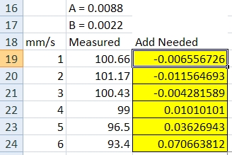
Thanks guys, cleared A & B and corrected my steps/mm to give correct extrusion at 1mm/s and ran the 100mm macro and the trend line gave A=0.0088 and B=0.0022 so I used those values and got the following results
After thinking about this for a bit it made me wonder if the correction should be recursive since you are not actually going to get the corrected amount but the corrected amount minus a % under due to the effect it is correcting? Anyway I don't have more time right now to mess with it but will mull that over.
-
Yes I gree with that. While you have got data points for the right amount of extrusion it is not necessarily at the right speed. Or at least that was the case the way I did it.
I'll check mine next time around but at the moment this needs to be with the head moving so non-linear extrusion is used. Be aware that with these moves the feed rate is soley referring to the motion axis and the extrusion is paced to complete within the move.
Other option is to alter the extrusion amount at each speed amount until you get a target extrusion length and calculate the required correction from that, rather than calculating the correction required to reach the target. Guess this would be more accurate.
-
I made a recursive spreadsheet that sums 6 iterations (yes way overkill, 3 would probably be sufficient) and set A & B back to 0 and started from scratch. The real life results are very good and probably within my measuring tolerance. Since there isn't a "c" in M592 I also had the spreadsheet correct the steps/mm based on the average of the real life results with M592 values in place.

-
@alexander-mundy That's great. Could you share your excel file?
I don't suppose you could post a picture of an actual extrusion pattern before and after the calibration to show the under extrusion at higher speeds and the corrected extrusion afterwards?