• Tags
  • Documentation
  • Order
  • Register
  • Login
Duet3D Logo Duet3D
  • Tags
  • Documentation
  • Order
  • Register
  • Login

Breakout board produces no 5v signals

Scheduled Pinned Locked Moved
Duet Hardware and wiring
4
16
1.6k
Loading More Posts
  • Oldest to Newest
  • Newest to Oldest
  • Most Votes
Reply
  • Reply as topic
Log in to reply
This topic has been deleted. Only users with topic management privileges can see it.
  • undefined
    leonknook
    last edited by 10 Oct 2018, 13:58

    I'm trying to drive an External stepper driver using the breakout board on a new Duet Ethernet. I assuming the signals from the board will be boost up from 3.3 to 5v but I'm afraid I misunderstood. When I measure with a multimeter there's 3.3v DC on the dir+ and dir- and en+ and en- when idle. When I try to move the y-axes there appears hardly no voltage on the pul+ and pul- signal. I want to drive a Nema 23 but for testing purposes I hooked up an Nema17. No movement at all. My external driver is a TB6600 see picture below and hier a piece of my config:
    ; Drives
    M569 P0 S1 ; Drive 0 goes forwards
    ;M569 P1 S1 ; Drive 1 goes forwards
    M569 P1 R1 T3
    M569 P2 S1 ; Drive 2 goes forwards
    M569 P3 S1 ; Drive 3 goes forwards
    M584 X0 Y5 Z2 E3 ; Apply custom drive mapping

    M350 X16 Y16 Z16 E16 I1 ; Configure microstepping with interpolation
    M92 X80 Y80 Z4000 E420 ; Set steps per mm
    M566 X900 Y900 Z12 E120 ; Set maximum instantaneous speed changes (mm/min)
    M203 X6000 Y6000 Z180 E1200 ; Set maximum speeds (mm/min)
    M201 X500 Y20 Z250 E250 ; Set accelerations (mm/s^2)
    M906 X800 Y5000 Z800 E800 I30 ; Set motor currents (mA) and motor idle factor in per cent
    M84 S60 ; Set idle timeout

    What can I do to boost up the signal to 5v if that's the problem.

    I'm stuck on this way to long so any help would be great.

    Kind regards,
    Leon.
    0_1539179722232_external stepperdriver.jpg

    undefined undefined 2 Replies Last reply 10 Oct 2018, 15:10 Reply Quote 0
    • undefined
      T3P3Tony administrators @leonknook
      last edited by 10 Oct 2018, 15:10

      @leonknook do you have a link to the datasheet for that external driver. most allow you to switch the -ve line of the pair and connect the +'ve line to 5V+ on the expansion board.

      www.duet3d.com

      undefined 1 Reply Last reply 11 Oct 2018, 07:04 Reply Quote 0
      • undefined
        dc42 administrators @leonknook
        last edited by dc42 10 Oct 2018, 15:29 10 Oct 2018, 15:28

        @leonknook said in Breakout board produces no 5v signals:

        M569 P1 R1 T3

        Did you mean to use P5 instead of P1 in that command? I think that is the real problem. Most external drivers work with the voltage levels provided by the expansion breakout board, but few if any work with the fast step pulse timing that the Duet uses by default.

        Duet WiFi hardware designer and firmware engineer
        Please do not ask me for Duet support via PM or email, use the forum
        http://www.escher3d.com, https://miscsolutions.wordpress.com

        1 Reply Last reply Reply Quote 1
        • undefined
          leonknook
          last edited by 11 Oct 2018, 06:56

          @dc42 said in Breakout board produces no 5v signals:

          M569 P1 R1 T3

          Thanks for the help but it did not work.

          I have tried all these settings also on P1.
          ; Drives
          M569 P0 S1 ; Drive 0 goes forwards
          ;M569 P1 S1 ;does not work
          ;M569 P5 S0 ;does not work
          ;M569 P5 R1 ;does not work
          ;M569 P5 R1 T1 ;does not work
          M569 P5 R1 T2 ;does not work

          M569 P2 S1 ; Drive 2 goes forwards
          M569 P3 S1 ; Drive 3 goes forwards

          M584 X0 Y5 Z2 E3 ; Apply custom drive mapping

          M350 X16 Y16 Z16 E16 I1 ; Configure microstepping with interpolation
          M92 X80 Y80 Z4000 E420 ; Set steps per mm
          M566 X900 Y900 Z12 E120 ; Set maximum instantaneous speed changes (mm/min)
          M203 X6000 Y6000 Z180 E1200 ; Set maximum speeds (mm/min)
          M201 X500 Y20 Z250 E250 ; Set accelerations (mm/s^2)
          M906 X800 Y5000 Z800 E800 I30 ; Set motor currents (mA) and motor idle factor in per cent
          M84 S60 ; Set idle timeout

          De second LED on de stepperdriver flashes like it is pulsing, but there is no movement in de stepper motor at all.
          Set the current on the stepper driver from 1 to 5 amp but no effect. Current in de config is set to 5000.

          Please help me out I don't want to struggle another day 😉

          regards,
          Leon.

          1 Reply Last reply Reply Quote 0
          • undefined
            leonknook @T3P3Tony
            last edited by 11 Oct 2018, 07:04

            @t3p3tony

            Here the specs if this is what you need for the TB6600.

            The stepperdriver is connected to a 48v dc powersupply.

            Specification
            Input Current: 0~5A
            Output Current: 0.5~4.0A
            Control Signal 3.3~24V
            Power (MAX): 160W
            Micro Step:1, 2/A, 2/B, 4, 8, 16, 32
            Temperature: -10~45℃
            Humidity:No Condensation
            Weight: 0.2 kg
            Dimension: 96 * 71 * 37 mm

            Or a link to this wiki here

            Please explain how I can switch to 5v, Is there somebody out there who have done this.

            Thanks for the help.
            regards,
            Leon.

            1 Reply Last reply Reply Quote 0
            • undefined
              adavidm
              last edited by 11 Oct 2018, 07:20

              according to that spec, 3.3v should work fine.

              Did you see @dc42's post?

              undefined 1 Reply Last reply 11 Oct 2018, 07:26 Reply Quote 0
              • undefined
                leonknook @adavidm
                last edited by 11 Oct 2018, 07:26

                @adavidm
                Yes I have changed P1 to P5 and nothing.
                I thought the drive mapping should do the job but I understand you have to assign the drive (on the break out board) in the M569 also.

                1 Reply Last reply Reply Quote 0
                • undefined
                  dc42 administrators
                  last edited by dc42 10 Nov 2018, 07:51 11 Oct 2018, 07:51

                  @leonknook said in Breakout board produces no 5v signals:

                  M569 P5 R1 T2 ;does not work

                  The breakout board handles the inversion of the enable signal, so you need R0 in that command, not R1. If it still doesn't work, try T4 instead of T2.

                  Duet WiFi hardware designer and firmware engineer
                  Please do not ask me for Duet support via PM or email, use the forum
                  http://www.escher3d.com, https://miscsolutions.wordpress.com

                  undefined 1 Reply Last reply 11 Oct 2018, 07:59 Reply Quote 0
                  • undefined
                    leonknook @dc42
                    last edited by 11 Oct 2018, 07:59

                    @dc42 said in Breakout board produces no 5v signals:

                    M569 P5 R1 T2

                    No, sorry no results. Second led is pulsing but it seems there is no current at all to drive the motor.
                    Extra info: the stepper driver has a 48v dc connection
                    The attached motor is a standard nema 17 to see if it works (must be later on a nema23)

                    ; Drives
                    M569 P0 S1 ; Drive 0 goes forwards
                    ;M569 P1 S1 ;does not work
                    ;M569 P5 S0 ;does not work
                    ;M569 P5 R1 ;does not work
                    ;M569 P5 R1 T1 ;does not work
                    ;M569 P5 R1 T2 ;does not work
                    ;M569 P5 R1 T5 ;does not work
                    ;M569 P5 R0 T2 ;does not work
                    M569 P5 R0 T4 ; does not work

                    M569 P2 S1 ; Drive 2 goes forwards
                    M569 P3 S1 ; Drive 3 goes forwards

                    M584 X0 Y5 Z2 E3 ; Apply custom drive mapping
                    M564 S0 H0

                    1 Reply Last reply Reply Quote 0
                    • undefined
                      dc42 administrators
                      last edited by dc42 10 Nov 2018, 08:05 11 Oct 2018, 08:04

                      Which is the "second LED" you refer to?

                      After you send the command to move Y, do you get +3.3V or greater on ENA+ relative to ENA- ? It should be the other way round after you reset the Duet and before you send the first command to move Y.

                      Duet WiFi hardware designer and firmware engineer
                      Please do not ask me for Duet support via PM or email, use the forum
                      http://www.escher3d.com, https://miscsolutions.wordpress.com

                      undefined 1 Reply Last reply 11 Oct 2018, 08:13 Reply Quote 0
                      • undefined
                        leonknook @dc42
                        last edited by leonknook 10 Nov 2018, 10:49 11 Oct 2018, 08:13

                        @dc42

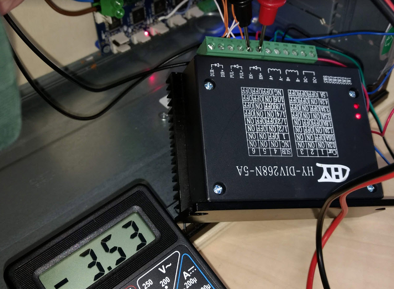
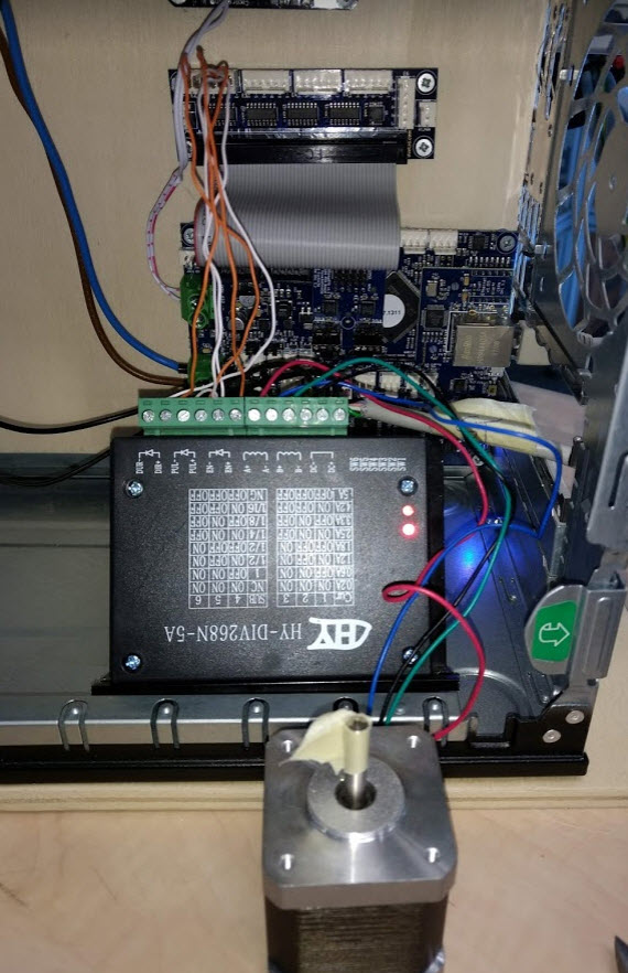
                        After a reset off everything I measure this -3.53v
                        After pushing the y move button the voltage change to plus +3.53v

                        The led down under is bright all the time
                        The led above is pulsing when pushing the move button.

                        Same measurement on the breakout board self without stepper driver connected.

                        0_1539245494118_en measure.jpg

                        1 Reply Last reply Reply Quote 0
                        • undefined
                          leonknook
                          last edited by 11 Oct 2018, 17:43

                          My problem is still not solved. If there are no options left over please let me know.
                          I will trow this well developed board out of the window and never look at it again.

                          1 Reply Last reply Reply Quote 0
                          • undefined
                            dc42 administrators
                            last edited by dc42 10 Dec 2018, 09:00 12 Oct 2018, 08:59

                            The LEDs suggest that your driver module is receiving the signals from the Duet. Are you certain that you have connected the stepper motor correctly, and set an appropriate microstepping and motor current on the switches? Does the motor spindle lock when the ENA voltage changes from negative to positive?

                            You can increase the drive voltage to 5V by connecting +ENA, +PUL and +DIR to +5V (which is available on the servo connector of the breakout board) instead of to the individual + outputs; but I really don't think that drive voltage is the problem.

                            Duet WiFi hardware designer and firmware engineer
                            Please do not ask me for Duet support via PM or email, use the forum
                            http://www.escher3d.com, https://miscsolutions.wordpress.com

                            undefined 1 Reply Last reply 18 Oct 2018, 14:04 Reply Quote 0
                            • undefined
                              leonknook @dc42
                              last edited by 18 Oct 2018, 14:04

                              @dc42
                              The TB6600 stepper driver seems to be not a suitable driver for the duet.
                              This week arrived the DM556 drivers and they work without any problems.

                              Thanks for all the help!

                              Kind regards,
                              Leon.

                              1 Reply Last reply Reply Quote 0
                              • undefined
                                leonknook
                                last edited by 7 Nov 2018, 10:24

                                To complete this thread for others. I had to use the 5v connection from the breakout board to make the DM556 to work properly. For some reason the 3.3v voltage from the +signals ENA PUL and DIR does not do the job for this driver.

                                1 Reply Last reply Reply Quote 0
                                • undefined
                                  dc42 administrators
                                  last edited by 7 Nov 2018, 11:03

                                  Thanks for the info. We will feed this input into planned design changes, and consider getting a TB6600-based driver to test.

                                  Duet WiFi hardware designer and firmware engineer
                                  Please do not ask me for Duet support via PM or email, use the forum
                                  http://www.escher3d.com, https://miscsolutions.wordpress.com

                                  1 Reply Last reply Reply Quote 0
                                  • First post
                                    Last post
                                  Unless otherwise noted, all forum content is licensed under CC-BY-SA