Large OX CNC belt driven laser cutter
-
@jgrouse said in Large OX CNC belt driven laser cutter:
The belts are GT2 3mm pitch
Is that what you were asking or are you asking what the spacing is on the grid pattern on the cut surfaces? Will measure in the morning with a caliper. I mentioned earlier that it does not vary with feed speed.
Laser is definitely going at 3kHz as you can hear the audible difference compared to running it at 1kHz and 200Hz (sound of the material being ablated). It's also not a CO2 laser, it is a 6W blue laser diode (NUBM44) with a Blackbuck 8M driver running from a filtered 12V DC source. 5V PWM pads can also take analog voltages from a trim pot.
Tested using 1/8 stepping with interpolation just on the X axis and apart from the motor being noisier it actually looks like the vertical banding is gone. Will test some more in the morning burning at various feed speeds.
-
Yes, I meant the pitch of the banding in the engraved/cut piece.
It's odd that it's better with x8 microstepping. The drivers on the Duet WiFi/Ethernet only support interpolation at x16 microstepping. You might want to try x16 without interpolation, or x32.
Duet WiFi hardware designer and firmware engineer
Please do not ask me for Duet support via PM or email, use the forum
http://www.escher3d.com, https://miscsolutions.wordpress.com -
nophead suggested lowering the microsteps which puzzled me however it did seem to do the trick. Not happy about 26.666 steps/mm for resolution though. Will also try 32 and 64 in the morning (11pm here now).
-
@dc42 Interpolation won't help if it can't achieve a low enough current for the microsteps near the crossing point due to the minimum on time, max off time, supply voltage and inductance. Or if the ripple current creates a big enough offset to distort at the crossing point.
The motor has a resistance of 1R2 and inductance 4mH. Current setting seems to be 2.2A for X. Is that peak?
I have no idea what mode the drivers are in as I have never run my Duet. Section 9.2 of the TMC2660 datasheet talks about tuning an offset for smooth zero crossing. Basically you can't just connect a random motor and expect it to be smooth motion. Does the firmware allow all these parameters to be tuned? Excuse my ignorance of it.
-
Hi @nophead,
Section 9.2 of the data sheet refers to constant off-time mode. If using that mode then you do indeed need to tune the settings to suit the motor. However, the default mode is spreadCycle (see section 9.1), and in that mode the driver is largely able to determine the chopper settings for itself. The exception is that sometimes the TOFF value needs to be reduced to avoid the chopper frequency being audible.
I don't think any of our users have ever reported getting the classic low-current-microstep issues that are frequently seen with DRV8825 drivers and less often with A4988 drivers.
All the chopper control parameters can be set using the M569 command.
The current set by M906 is peak. We chose peak because when we introduced the Duet WiFi, the standard way to talk about motor current using the drivers of the time (A4988, DRV8824 etc.) in 3D printers was to refer to peak current.
-
After some more testing it appears that the ridges are due to fluctuations in the laser power. If you look at the image below I sped up the job twice 2/3's down (X sweeps) and you can see the ridges spacing out.
 At 1000mm/min the ridges are about 0.62 mm apart. I worked out that a 50Hz hum in the power supply would give me ridges that are 0.333 mm ridge to ridge so this looks like something close to 25Hz? Here in AU all AC mains is 50Hz. I put a digital oscilloscope on the 12V source and it's extremely clean with no low frequencies on it. Only other source of grief could be the laser driver itself ("BlackBuck 8") or the PWM signal which is now set at 6kHz PWM frequency? I can't put a cap on the PWM to smooth it out as the sharp edges of 3D engraved shapes would end up tapered. I cannot imagine why any 50Hz hum would end up on the PWM? Perhaps the GND pin on the PWM is floating? Either way I will need to get the oscilloscope onto it and see what it is producing.
Belts on the router are now doubled up with one in the base of the grove facing up and glued down to help dampen sudden moves. Last test was with the microstepping set to 256 for x and y (I0).
Another passing thought is that the air assist is pulsing rather than being a constant stream. It most likely puts out a puff every second pulse from the 50Hz AC mains source? I did turn if off briefly in that engrave above which resulted in a few dark horizontal lines, but when flames started heading for the air nozzle I had to get it back on again. Might experiment with compressing the tank fully and then letting it out slowly with the pump off during the cut to see if that makes any difference? -
No low frequencies on the PWM out of the Duet. Tried letting the air compressor fill and then ran with it off. Still had ridges. Quite a puzzle.
-
The bottom two ridges look exactly like a drive belt. Do you have the option to use a belt that has not been doubled up?
-
@ayudtee - The large CNC router I have was set up originally with single belts and I still had this issue. If it was belt related the pattern size would be consistent regardless of the feed speed. It just looks like either the laser driver is creating a 25Hz hum on the power output or the air compressor is creating a 25Hz puff rather than a constant stream. Interestingly if I lower the max power to 50/255 I don't get the ridges so possibly the BlackBuck 8M with the temp sensor fitted is doing some power regulation at 25Hz? Might try turning down the max amps and see what that does? Also posted this question on the Laser Pointers Forum to see if anyone has had this issue as well. Plenty of NUBM44 6W blue laser owners on there.
-
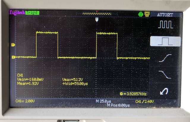
Just read up on the BlackBuck 8M laser driver and it states that running higher than 5V on the MOD input is not advisable. Looking at the Vmax of 5.12V that's exactly what is happening. Might put a 10k trim pot across the input to lower the max voltage of the PWM to just below 5V and see if the ripple vanishes? Unfortunately the pad on the board popped off when I went to remove the wire so now I have to wait for the replacement driver to arrive in the mail. Made in Russia so not sure how long postage takes to AU?
Wish they made a slightly bigger version with larger pads on the board?
-
I'm also looking into driving the laser with an actual analogue signal rather than PWM which just blasts the laser a max power in varying pulses. The I2C MCP4725 DAC is a 10bit digital to analogue chip which can be sent M260 I2C commands to set the output voltage. Since I've written my own app to turn grey scale images to GCode I'll modify it to set the power before each G1.
-
@jgrouse said in Large OX CNC belt driven laser cutter:
I'm also looking into driving the laser with an actual analogue signal rather than PWM which just blasts the laser a max power in varying pulses. The I2C MCP4725 DAC is a 10bit digital to analogue chip which can be sent M260 I2C commands to set the output voltage. Since I've written my own app to turn grey scale images to GCode I'll modify it to set the power before each G1.
Does the laser controller accept an analog input? If it accepts both analog and PWM through the same input, it may be just smoothing the PWM.
Have you calculated whether the latency of the I2C transactions will be low enough?