• Tags
  • Documentation
  • Order
  • Register
  • Login
Duet3D Logo Duet3D
  • Tags
  • Documentation
  • Order
  • Register
  • Login
  1. Home
  2. jgrouse
  • Profile
  • Following 0
  • Followers 1
  • Topics 10
  • Posts 66
  • Best 1
  • Controversial 0
  • Groups 0

jgrouse

@jgrouse

1
Reputation
4
Profile views
66
Posts
1
Followers
0
Following
Joined 15 Sept 2016, 04:30 Last Online 1 Nov 2021, 09:12

jgrouse Unfollow Follow

Best posts made by jgrouse

  • BMP183 SPI sensors as bed probe

    This is more of an announcement of a new z probe system rather than a question for help -

    I've been playing with piezo sensors to detect when the nozzle touches the bed surface (mounted under the bed) when performing bed leveling and I ran into some drawbacks with that system:

    1. there has to be a shock of some form, like a tap, for the sensors to detect the nozzle hitting the bed. This requires the nozzle to be approaching fast enough for it to register. If it misses the impact, the increase in pressure as the nozzle drives into the bed surface never gets detected till things start to go pop or the steppers skip.
    2. it's not actually measuring the pressure of the nozzle down onto the bed, just the point of impact. Fine if it gets that point each and every time.
    3. noisy motors/mechanics trigger the sensors.

    Now, I can imagine this would work better if the surface of my bed was hard like glass but it's PEI stuck to magnetic rubber pads so I can lift the surface off. I don't get the required "tap".

    Putting that to one side I came up with what I think is an extremely good alternative - barometric pressure sensors with a rubber boot over the sensor chip (sealed with silicone). Surprisingly this created an incredibly sensitive sensor for any pressure down on that tiny rubber boot over the sensor. In my case I wanted three modules under the bed so had to use SPI rather than i2c as that gives me multiple assigned SPI CS pins on the Ardunio board rather than being limited to two addresses / two modules. The BMP183 from Adafruit came up as an option so went with three of those. I 3D printed a rubber boot to fit over the chip on the module using TPE and glued it down with silicone to ensure a tight seal. The Arduino code gets the current pressures on each module in a quick loop and triggers pin 3 high when any of them detect a change of 0.3 Hpa from the last measurement. With the chip sealed under this boot the smallest pressure change trips it off. Fortunately the only thing that triggers them is actual pressure, not bumps or vibrations. Compared to the raw piezo sensors they appear to be just as sensitive, without the false triggers. That seal on the rubber boot is critical as the smallest of leaks reduces the sensitivity dramatically. I can approach the bed surface as slow as I want and it will still trigger the moment there is the smallest amount of pressure. Movements in the Y axis have no effect on the sensors. However, acceleration movements in the Z axis will trigger them, so for printers with the bed moving on the z axis this would probably not be a good solution, unless that motion was very slow. In that case you could probably mount a single sensor on the hot end.

    I've also tried resistor pressure pads under the hot end nozzle but these were not as sensitive to pressure as this new design.

    These modified modules then get mounted into 3D printed linear bearing blocks with a slot in the top of them to allow downward pressure to directly press on the rubber boots under each Y axis mount point. All three hook up to an Arduino mini stuck on the base frame of the bed. This then has three wires back to the Duet Wifi - 5V, GND and signal.

    The three modules set me back about $55 AUD in total and I already had plenty of Arduino mini's sitting about doing nothing. I thought about using a 3.3V Arduino however these run at 8MHz rather than 16 and I need the trigger to be as quick as possible. I'm going to tap into the 5V pin on the Duet to drive the Arduino for now.

    What I want to know is if the Z Probe IN pin on the Duet probe connector can tolerate 5V in? Should I set up a voltage divider to drop that down to 3.3V? The write up on connecting the BLTouch suggests using a 240 ohm between the probe GND and IN pins however I would have thought an additional resistor between IN and the OUT of the 5V pin on the Arduino would complete the voltage divider. Wouldn't a -10k -|- 5k- divider be closer to the mark and still provide the amps to be detected by the Probe IN pin?

    Once I get this all working nicely I'll post the 3D printed parts and a write up on Thingiverse if anyone wants to try it out. Down the track I will probably come up with an integrated PCB with connectors out to each of the three modules. There are probably more sensitive pressure sensor modules out there but these seem ok.

    First test will be to create surface maps one after the other and compare the CSV's to see how consistent the probe points are.

    I'll post results when I have this all mounted in the printer.

    posted in Duet Hardware and wiring
    undefined
    jgrouse
    22 Sept 2018, 08:16

Latest posts made by jgrouse

  • RE: V3.3 FW on Duet Wifi - Bed not heating fast enough error message

    @jay_s_uk - was hoping to avoid that. Ok, it's running now. Will post back in a few days when it's done. There really has to be an easier way. Anyone got some PID setting examples from their 300x300mm 240V AC heated bed?

    posted in Tuning and tweaking
    undefined
    jgrouse
    1 Nov 2021, 09:12
  • V3.3 FW on Duet Wifi - Bed not heating fast enough error message

    Decided to drop a Duet Wifi board into a Sidewinder X1 today and after updating the FW to 3.3 I'm getting an odd message after setting the bed to 60C saying "Error: Heater 0 fault: temperature rising much more slowly than the expected 1.2°C/sec" 1.2C/sec is actually quite fast for a 310x310 bed. I did try the auto tuning process on the bed however I just seemed to stay in a heat/cool loop for 2 hours so canned it. It's currently set to use bang-bang so the SSR is delivering the full 240V AC to the heater with no backing off till it gets to 60C. Is there some way to bypass this error check or at least tweak it to expect at least 0.5C/sec or something smaller?

    Super irritating having to reset the fault and brute force it to try again and again till I get 60C.

    posted in Tuning and tweaking
    undefined
    jgrouse
    30 Oct 2021, 10:10
  • RE: Job Status don´t work

    @dc42 - the wifi connection has been very reliable since I put Google Wifi points around the house and one in the garage. Before that it would drop regularly. But that was the beginning of the year and I had this issue before then. Attached are my config files. Hopefully you can spot something there? Should I blow away the web server files on the SD and recreate the folder from the latest zip resources?2_1557270693645_config.g 1_1557270693645_StartPrint.g 0_1557270693645_EndPrint.g

    posted in Duet Web Control
    undefined
    jgrouse
    7 May 2019, 23:12
  • RE: Job Status don´t work

    I've had this issue for ages now and I was hoping the last updates I just applied would get my job status to work but it's still not showing any info during 3D prints.

    Firmware Name: RepRapFirmware for Duet 2 WiFi/Ethernet
    Firmware Electronics: Duet WiFi 1.0 or 1.01
    Firmware Version: 2.03beta3 (2019-03-25b6)
    WiFi Server Version: 1.23
    Web Interface Version: 1.22.6

    Not sure what else to try? Is there any possibility that since updating to Simplify3D V4.X the code stopped supplying the required GCode for status info?

    Attached are my relevant settings. Also attached is a sample gcode file from Simplify3D 4.1.2 0_1556848471785_config.g 0_1556848492115_StartPrint.g 0_1556848538450_Nitro 200 frame clip.gcode

    posted in Duet Web Control
    undefined
    jgrouse
    3 May 2019, 01:57
  • resume.g and using a laser

    Hi,

    I'm finding that when I pause and then resume in the middle of a laser cut, the resume turns on the laser at full power as it moves back to the point it left. This is the content of my resume.g file -

    M3 S0
    G1 R1 X Y Z30 S0 F9000

    As you can see I am forcing zero power on both lines. It's like the R1 parameter is ignoring the laser power and just overriding with S255?

    Bug or wrong command to go back to the point I paused on?

    Duet Wifi is in laser mode with this command -

    M452 P6 R255 F6000 I0

    Firmware Name: RepRapFirmware for Duet 2 WiFi/Ethernet
    Firmware Electronics: Duet WiFi 1.02 or later
    Firmware Version: 2.02RC3(RTOS) (2018-10-17b2)
    WiFi Server Version: 1.21
    Web Interface Version: 1.22.4-b1

    posted in Laser Cutters
    undefined
    jgrouse
    3 Dec 2018, 02:08
  • RE: Large OX CNC belt driven laser cutter

    I'm also looking into driving the laser with an actual analogue signal rather than PWM which just blasts the laser a max power in varying pulses. The I2C MCP4725 DAC is a 10bit digital to analogue chip which can be sent M260 I2C commands to set the output voltage. Since I've written my own app to turn grey scale images to GCode I'll modify it to set the power before each G1.

    posted in Laser Cutters
    undefined
    jgrouse
    12 Nov 2018, 04:55
  • RE: Large OX CNC belt driven laser cutter

    Just read up on the BlackBuck 8M laser driver and it states that running higher than 5V on the MOD input is not advisable. Looking at the Vmax of 5.12V that's exactly what is happening. Might put a 10k trim pot across the input to lower the max voltage of the PWM to just below 5V and see if the ripple vanishes? Unfortunately the pad on the board popped off when I went to remove the wire so now I have to wait for the replacement driver to arrive in the mail. Made in Russia so not sure how long postage takes to AU?

    Wish they made a slightly bigger version with larger pads on the board?

    posted in Laser Cutters
    undefined
    jgrouse
    11 Nov 2018, 23:12
  • RE: Large OX CNC belt driven laser cutter

    @ayudtee - The large CNC router I have was set up originally with single belts and I still had this issue. If it was belt related the pattern size would be consistent regardless of the feed speed. It just looks like either the laser driver is creating a 25Hz hum on the power output or the air compressor is creating a 25Hz puff rather than a constant stream. Interestingly if I lower the max power to 50/255 I don't get the ridges so possibly the BlackBuck 8M with the temp sensor fitted is doing some power regulation at 25Hz? Might try turning down the max amps and see what that does? Also posted this question on the Laser Pointers Forum to see if anyone has had this issue as well. Plenty of NUBM44 6W blue laser owners on there.

    posted in Laser Cutters
    undefined
    jgrouse
    10 Nov 2018, 23:15
  • RE: Large OX CNC belt driven laser cutter

    No low frequencies on the PWM out of the Duet. Tried letting the air compressor fill and then ran with it off. Still had ridges. Quite a puzzle.
    0_1541828812295_IMG_3961.jpg

    posted in Laser Cutters
    undefined
    jgrouse
    10 Nov 2018, 05:48
  • RE: Large OX CNC belt driven laser cutter

    After some more testing it appears that the ridges are due to fluctuations in the laser power. If you look at the image below I sped up the job twice 2/3's down (X sweeps) and you can see the ridges spacing out.
    0_1541825902224_IMG_3954.jpg 
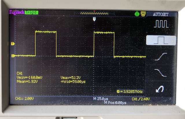
At 1000mm/min the ridges are about 0.62 mm apart. I worked out that a 50Hz hum in the power supply would give me ridges that are 0.333 mm ridge to ridge so this looks like something close to 25Hz? Here in AU all AC mains is 50Hz. I put a digital oscilloscope on the 12V source and it's extremely clean with no low frequencies on it. Only other source of grief could be the laser driver itself ("BlackBuck 8") or the PWM signal which is now set at 6kHz PWM frequency? I can't put a cap on the PWM to smooth it out as the sharp edges of 3D engraved shapes would end up tapered. I cannot imagine why any 50Hz hum would end up on the PWM? Perhaps the GND pin on the PWM is floating? Either way I will need to get the oscilloscope onto it and see what it is producing.
    Belts on the router are now doubled up with one in the base of the grove facing up and glued down to help dampen sudden moves. Last test was with the microstepping set to 256 for x and y (I0).
    Another passing thought is that the air assist is pulsing rather than being a constant stream. It most likely puts out a puff every second pulse from the 50Hz AC mains source? I did turn if off briefly in that engrave above which resulted in a few dark horizontal lines, but when flames started heading for the air nozzle I had to get it back on again. Might experiment with compressing the tank fully and then letting it out slowly with the pump off during the cut to see if that makes any difference?

    posted in Laser Cutters
    undefined
    jgrouse
    10 Nov 2018, 05:16
Unless otherwise noted, all forum content is licensed under CC-BY-SA