Duet Wifi 1.04 and NPN NO inductive sensor
-
Hello everyone,
I got my duet a few days ago and i am trying to find out how to connect the sensor i have(LJ12A3-4-Z/EX) to the duet.
I am not keen on electronics and before risking to fry anything i would like to validate.
I have searched through the forum as well as other sources. Most sources state that you cannot connect an inductive sensor directly to the duet and you would need a resistor or diode, or divide voltage. Thus on the "Connecting a Z probe" article i read for NPN output normally-open inductive sensor that revision 1.04 or later of Duet 2 WiFi "you can connect the output of the sensor directly to the IN pin of the Z probe connector. You must also connect a pulldown resistor between IN and GND of the Z probe connector. 10Kohms is a suitable value."This is still not clear to me as my electronics know how is low. Is there some practical image of an actual sensor being connected that way and not a diagram? Eg how do you add the pulldown resistor? Solder it between the IN and GND? I have seen different diagrams from people that tried and i am not sure which one is the one to follow. Also i saw DC42 mention that you should connect the GND to the always on fan if i am not mistaken. What is the z probe connector for if you have to connect the cables to different positions on the board?
Sorry for the questions, it might be simple to some people, but i am really afraid not to fry anything so i have to validate before doing anything noobish.
Thank you in advance.
-
@gpetropoulos I use a relay module: https://www.amazon.com/gp/product/B00MMW0XWY
That way I don't need to worry about resisters or diodes. -
@Stephen6309 Thank you for the reply. So i just get a relay? I am on 24V psu. Does that change things?
Can you please show me a picture of the connections? How do you connect on the relay and how on the board. -
As your Duet is revision 1.04 then it is safe to connect the sensor output directly to the Z probe IN pin. But be very careful to connect it to the IN pin on the Z probe connector, not any other pin! The IN pin will tolerate 24V, the other pins will not.
Duet WiFi hardware designer and firmware engineer
Please do not ask me for Duet support via PM or email, use the forum
http://www.escher3d.com, https://miscsolutions.wordpress.com -
@dc42 Either i was looking at another page or something changed. I checked again the article
https://duet3d.dozuki.com/Wiki/Connecting_a_Z_probe#Section_NPN_output_normally_open_inductive_or_capacitive_sensor
and i can no longer see the text saying i need to add a pulldown resistor. Also i saw on a post about adding a diode. This is not mentioned in the wiki. Is it needed or not?So do i need a pulldown resistor or a relay as mentioned above? Or can i connect the 6-36v inductive sensor directly to duet and especially on the z probe sensor?
Can you please provide some diagram to what i need to connect?
Based on the wiring diagram for the v1.04i see the z probe connector shows z probe in, gnd, z probe mod, +3.3V.
My inductive sensor model(LJ12A3-4-Z/EX) with blue, brown and black wires. Normally this would be
Brown 24vdc+, Blue 24vdc-, and black is signal.
So i need to connect the black(signal) to the z probe IN pin. Blue(-) to GND on always on fans and brown(+) on V_Fan on always on fans? Or do the + and - cables connect somewhere else? Can the always on fans take this config by default or do i need to change some jumper or something?
Is the correct wiring as shown in this image?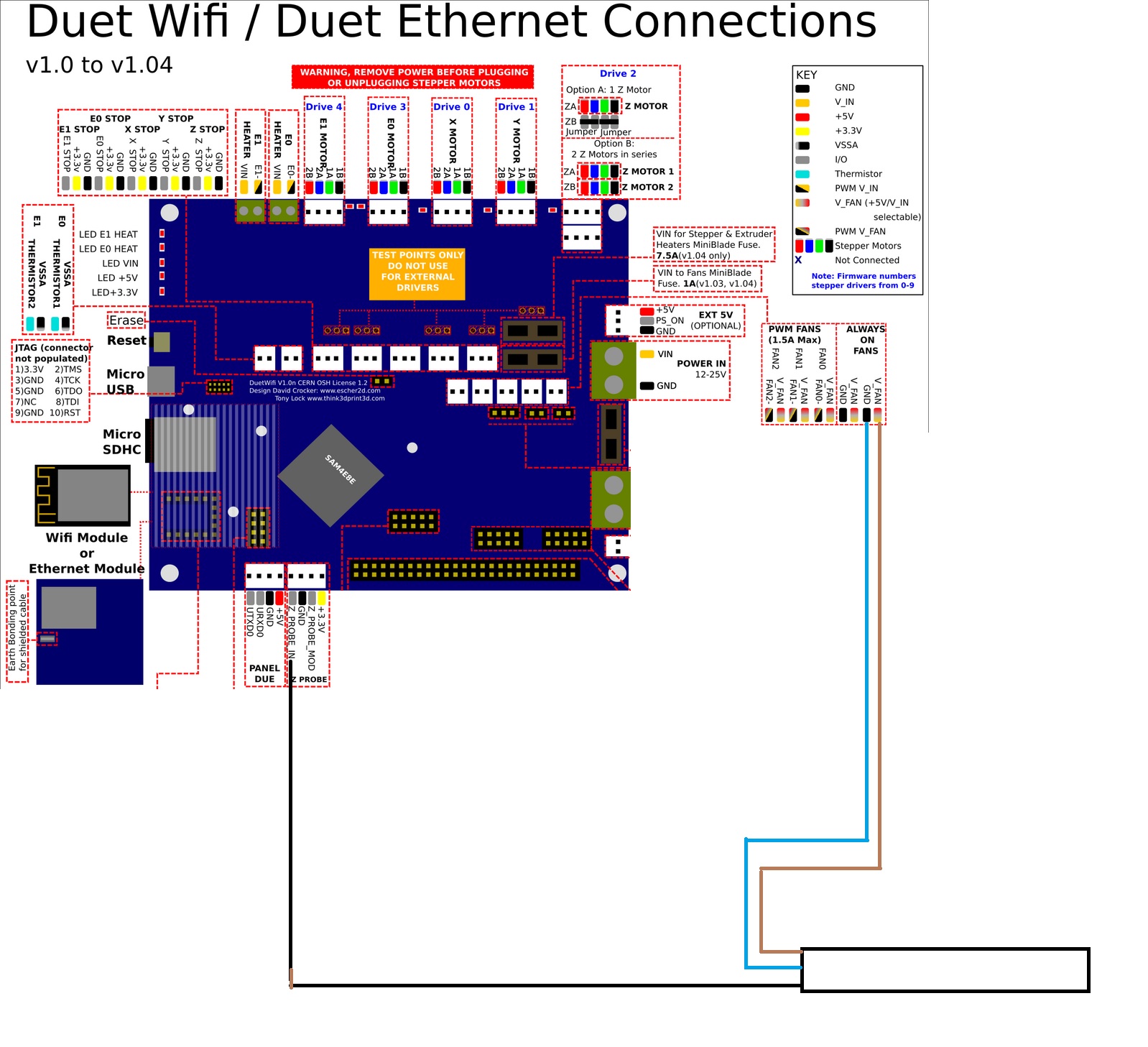
I have read this thread but my conclusion to what the right way is, is not clear. (https://forum.duet3d.com/topic/6779/pnp-inductive-sensor-and-wiring/18)
-
That's correct, the output of an NPN output sensor can be connected directly to the IN pin of the Z probe connector of a revision 1.04 board.
A pulldown resistor is needed when using a PNP sensor - although for PNP sensors I still recommend using a voltage divider (e.g. two 10K resistors) because of the risk of mis-wiring.
Duet WiFi hardware designer and firmware engineer
Please do not ask me for Duet support via PM or email, use the forum
http://www.escher3d.com, https://miscsolutions.wordpress.com -
@dc42 I might overdo it and excuse me for this.
So i connect my NPN sensor like the diagram above?
No pulldown resistors or anything.Just plug the black(signal) to the z probe IN pin. Blue(-) to GND on always on fans and brown(+) on V_Fan on always on fans?
Thank you very much for your patience and support.
-
@gpetropoulos said in Duet Wifi 1.04 and NPN NO inductive sensor:
@dc42 I might overdo it and excuse me for this.
So i connect my NPN sensor like the diagram above?
No pulldown resistors or anything.Just plug the black(signal) to the z probe IN pin. Blue(-) to GND on always on fans and brown(+) on V_Fan on always on fans?
Thank you very much for your patience and support.
Correct. When using a pre-1.04 board we recommend connecting a Schottky diode between the NPN sensor output wire and the Z-probe connector IN pin. That is to protect the Duet if the sensor ground connection breaks.
-
@gpetropoulos I wired the endstop connection to COM & NC. On the other end, the DC+ & DC- has the power from the power supply and the sensor is to the same place for power. The signal wire from the sensor goes to the IN connection. The high/low trigger is set to the high side.
A 24vdc version is this one: https://www.amazon.com/dp/B01J0KVMEI
-
Hello,
I have set up my inductive NPN NO sensor as described. It seems to work when sensing metals, the led turns on, but it is having a hard time through a buildtak sheet. May i please validate what the voltage through the always on fans is? So my psu is 24 V, and i have not touched any jumper on the board(1.04) so the always on fans provide 24V right? If that is correct i may need to find a stronger sensor, or different type.
-
The voltage on the always-on fan connectors is either VIN or 5V, depending on the position of the V_FAN jumper. Genuine Duets should have it set to VIN as shipped because this is how we test them.
-
I have found this thread very useful, as I use the same proximity sensor (LJ12A3-4-Z/BX). My printer is now running properly and I am one step closer to homing the Z-Axis. So, thanks!