AKL+ switch Z probe crash (delta printer)
-
Hello everyone.
Finally I finished the wiring of my anycubic delta kossel linear plus. I connected the Z probe stock switch to E0. The led on the board works, it lights up when I press the probe.
I used the RepRap online config tool. Uploaded the files to DWC.
In the DWC "Z probe" when "0" is not pressed and "1000" is pressed.
This is the part in config.g:M558 P4 H30 F900 T6000
G31 P500 X0 Y0 Z16.2
M557 R110 S20So from what I read on the forum everything should be ok.
I do not have Config-override.g files because it's the first ever automatic calibration.This is the problem:
I start the auto calibration delta and the first point on the bed is ok. The probe activates and moves to the second point.
The second point is not detected and therefore the motors push the probe downwards. The probe is crushed, and I am forced to turn it off to avoid further damage.Can you kindly help me complete the auto calibration?
thank you -
My guess is that you have a wiring issue and the connection between the switch and the Duet is being lost sometimes depending on the XY position of the effector. Next time you run auto calibration, watch the LED on the Duet to see whether it lights when the probe contacts the bed at the second probe point.
If your switch has both normally-open and normally-closed contacts, then it's safer to use the normally closed contacts, so that if the connection fails then it will look as though the probe is triggered. You would need to include i1 in the M558 command if you use the NC contacts, and the LED will work in reverse.
You can reduce motor current while debugging this, to minimise damage if the probe fails to trigger.
-
Thanks for the quick reply.
Unfortunately I had already tried to insert I1 to reverse the probe ... but it did not help.Updates of my first post:
-
I tried to send a G30 following the instructions on the wiki duet.
When I press the probe with my finger it does not stop and continues to go down.
Moreover it does not go straight in point X0 Y0 but moves during the descent. -
I tried to change home height to see what happened during the calibration after the second crash point.
This way the calibration went on and I saw that the printer is moving strangely.
the probe does not move by turning and going towards the center or it does not move by lines and then goes on (I do not know how it should be done on a delta).
It happens that the probe goes to the edge of the bed 120 mm (even if I gave him 110 mm print radius) he presses the switch.
Then it moves at half height slowly, moves quickly to the crash point and presses.
Then it goes to probe a new point on the edge of the bed and returns to the point to move at half height.
Then it returns to the same point of crash and presses.
All calibration in the same way.
I do not think I was wrong in the compensation section.
I try to insert my config also.
If you see something wrong, could you let me know?0_1545937092358_bed.g 0_1545937117144_config.g 0_1545937124615_homedelta.g 0_1545937236573_pause.g 0_1545937239644_resume.g -
-
@mroppip said in AKL+ switch Z probe crash (delta printer):
I tried to send a G30 following the instructions on the wiki duet.
When I press the probe with my finger it does not stop and continues to go down.
Moreover it does not go straight in point X0 Y0 but moves during the descent.Do you have deployprobe.g and retractprobe.g files in /sys on the SD card? if so, delete them unless you created them yourself for a specific purpose.
Duet WiFi hardware designer and firmware engineer
Please do not ask me for Duet support via PM or email, use the forum
http://www.escher3d.com, https://miscsolutions.wordpress.com -
@dc42 said in AKL+ switch Z probe crash (delta printer):
Do you have deployprobe.g and retractprobe.g files in /sys on the SD card? if so, delete them unless you created them yourself for a specific purpose.
you guessed @dc42 !
I had those files. I deleted them and the calibration was successful.-
After the calibration I saved and created the config-override.g.
now when I command "home all" the printer gives me these coordinates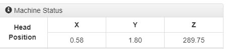
Why are X and Y not zero? -
during the calibration I tried to change diagonal rod length, because it was not probing the print radius that I had set. I measured the diagonal rod lenght between the center of the rod joints.
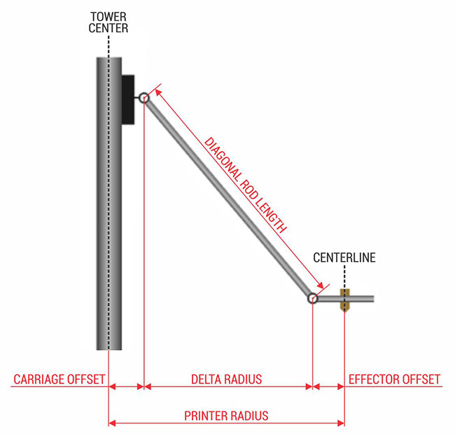
I was wrong? Should this measure be taken in another way to be precise?
why on the Rap Rep config tool says "distance between the center of your towers and the joint at the effector"?
thanks for the support
-
-
You can take the correct lengths for the AKL+ from the Marlin firmware (see https://github.com/MarlinFirmware/Marlin/blob/1.1.x/Marlin/example_configurations/delta/Anycubic/Kossel/Configuration.h#L577).
I would reduce the Z height to some safe value and then fix it through calibration (see https://duet3d.dozuki.com/Wiki/Calibrating_a_delta_printer).
-
@oliof said in AKL+ switch Z probe crash (delta printer):
You can take the correct lengths for the AKL+ from the Marlin firmware (see https://github.com/MarlinFirmware/Marlin/blob/1.1.x/Marlin/example_configurations/delta/Anycubic/Kossel/Configuration.h#L577).
I would reduce the Z height to some safe value and then fix it through calibration (see https://duet3d.dozuki.com/Wiki/Calibrating_a_delta_printer).
Thank you @oliof But I've already seen these links.
Also some measures are not correct.
267 mm is the measurement of the rods between the center of the joints (not 271.5 mm).I still did not understand the measure to be put in the configurator online ... because it seems that wants the measure starting from the center of the tower.
I await the answer to the questions above
-
The values that the configurator needs are:
- M665 L parameter: an accurate value for the diagonal rod length (measured between bearing centres).
- M665 R parameter: an approximate values for the delta radius
- M665 H parameter: an approximate value for the height of the nozzle above the bed when all 3 homing switches are triggered
- M665 B parameter: the radius of the bed which tha nozzle can reach safely
R and H will be fine-tuned by auto calibration.
After after you have calibrated, immediately after the homing move the effector will not be exactly in the centre unless all the endstop corrections are zero. The standard delta homing file generated by the configurator moves the effector down 5mm and centres it immediately after homing.
Duet WiFi hardware designer and firmware engineer
Please do not ask me for Duet support via PM or email, use the forum
http://www.escher3d.com, https://miscsolutions.wordpress.com -
@dc42 thank you!
Always exhaustive")