Auto Delta Calibration / Mesh Grid Compensation
-
The probe is an LJ12A3-4-Z/AY and gets powered through 12v, so that shouldn't be an issue. It works fine when doing single point measurements and/or calibration.
-
whats the surface?
are you probing with the bed hot? -
Build Tak and yes, I probe with the bed at 60°.
The point is: The mesh grid compensation seems to measure with a systematic error along the X-axis. It seems highly unlikely, that this type of error is caused by the bed material, the probe properties and/or the temperature.
My guess is that it is caused by the print-head-assembly changing its tilt very slightly when moving along X. Since this would be caused by the actual printer geometry, which I can't really change, there would have to be a way to offset that.
I think, that might be solvable with some delta geometry definition?
Unfortunately, the duet3d.dozuki.com website seems down at the moment.
-
inductive senors are prone to heat. try the probing before the heatup.
see https://www.youtube.com/watch?v=il9bNWn66BY&t=389s -
Ok, did a few things:
- Ran calibration again, but this time with a much higher radius (going to the very limit of the build plate) and using 6 points and 6 parameters instead of 3 and 3. This yielded the following geometry:
Diagonal 278.000, delta radius 146.517, homed height 230.255, bed radius 110.0, X -1.005°, Y -0.038°, Z 0.000°
The thing to note here is the X-tilt of ~1°, which was not detected during the previous calibrations. - Run mesh grid compensation again, it now shows a much cleaner bed topology (but not quite there yet):

I think I'll have to tinker some more with the X/Y/Z pillar tilt compensation to get those number down more...
- Ran calibration again, but this time with a much higher radius (going to the very limit of the build plate) and using 6 points and 6 parameters instead of 3 and 3. This yielded the following geometry:
-
HOWEVER... the nozzle still has a height difference of about 1mm between the points on one side of the bed vs. the other. I must be doing something seriously wrong....
-
have a look at this. http://boim.com/DeltaUtil/CalDoc/Calibration.html
i found that a delta benefits greatly from a nozzle probe.
i use a Automatic Leveling Module Film Pressure Probe
can be bought for around 2 euro. -
Yeah, I'm thinking of going for a piezo nozzle probe (https://www.precisionpiezo.co.uk/). I'll get it and will update this post with the results...
-
@remopini said in Auto Delta Calibration / Mesh Grid Compensation:
HOWEVER... the nozzle still has a height difference of about 1mm between the points on one side of the bed vs. the other. I must be doing something seriously wrong....
That's the classic sign of using a probe offset from the nozzle, and the effector tilting a little as it moves in the XY plane.
Also the ridges and valleys along the X direction in the height map indicate that you have a small amount of backlash in the motion mechanism.
-
The slider in the Trium has a fair bit of play or backlash in its construction or mating with the groove or bed in the extruded tower .
I found that there was a lot of roll when the stage got out to the edges of the bed , the two closest towers tended to roll in towards the stage and then when moving to the other extreme rolled out . Not so noticeable when printing in the middle though they did wiggle when doing rapid moves .
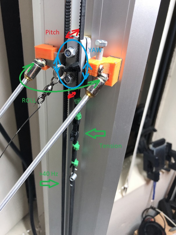
( this can really effect the offset probe)The sliders also have a bit of yaw and pitch . Those two can be fixed by increasing belt tension considerably more than what we were told to do.
I didn't realize how light my tension was until I ended up with one belt wearing out a bit and it started riding on top of the gear rather than in it . Causing all kinds of ghostly print issues as it came and went . It increased the travel distance at random on the X tower
To increase tension set the idle or continuous side of the belt to greater than 40hz at least ( mine is at 44hz) it should twang a bit like a bass string. Use the Iphone App EasyTension , it has a frequency meter for belts!
attached is a picture of what I did. Which pretty well stabilized the slider
Orange blocks are outriggers backed with adhesive teflon sliders (furniture hardware leg protectors)
Gray block made the belts parallel and virtually eliminated pitch and yaw
The green arrow is my disposable tension device a heavy duty tiewrap which is walked closed with a pair of pliers while twanging the belt
-
@digid Thank you for that very thorough answer :). It's probably the next stage in my "get the Trium up to snuff" masterplan.
@dc42 Thank you for that explanation... was fearing something like that...I replaced a bunch of stuff:
- E3D v6 Hotend (instead of the stock crappy one)
- Nozzle Piezo probe (instead of the inductive crappy one)
Now, my bed leveling looks like this:

I think I'm pretty happy with that...
")