Invert the Enable signal polarity
-
Hi all,
I'm using Duet Wifi Ver1.01 which connected to external motor drivers.
The drivers i'm using must accept LOW in the Enable pin in order to enable the motors, and HIGH in the Enable pin in order to disable motors.The problem is that for some reason the Enable pin on my Duet WiFI are by default:
X (0) - High (3.3[v])
Y (1) - Low (0[v]) (which is perfect)
Z (2) - High (3.3[v])in order to invert the X&Y Enable pin
I tried these command in the firmware "config.g" file:
M569 P0 S0 R0;
M569 P1 S1;
M569 P2 S1 R0;and also
M569 P0 S0 R1;
M569 P1 S1;
M569 P2 S1 R1;and also..
M569 P0 S0 R-1;
M569 P1 S1;
M569 P2 S1 R-1;Unfortunately that didn't had any effect.
any suggestions ?
Appreciate your support.
-
Where on the Duet WiFi have you connected the external motor drivers? You should connect them to the expansion connector, e.g. the E2_STEP/E2_DIR/E2_EN pins and similarly for E3 and E4. Then use M584 to map axes X,Y.Z to drivers 5,6,7 (and also map extruders to the remaining drives) and use M569 to set drivers 5,6,7 to have active low enables.
-
Hi David,
Appreciate your reply.
I connected the External drivers to the 3 through hole for each axis (X,Y,Z) after I soldered male headers to these holes.
Picture attached:
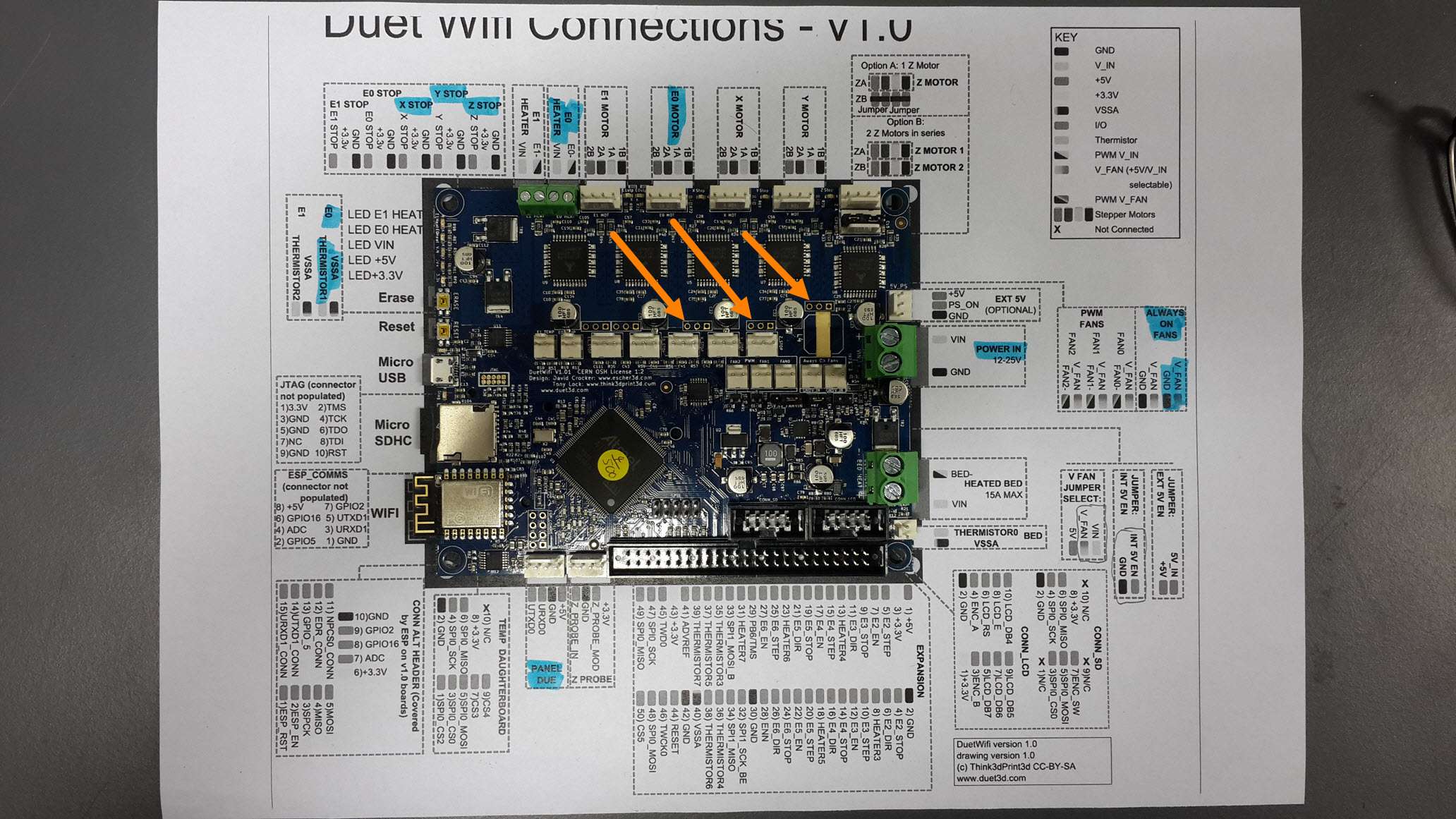
Now that you say it shouldn't be connected this way, I will try to connect the external drivers to the expansion connector the way you said so:
X:
E2_EN
E2_DIR
E2_STEPY:
E3_EN
E3_DIR
E3_STEPZ:
E4_EN
E4_DIR
E4_STEPI have another question - What is the purpose of the E1_STOP, E2_STOP and etc.. pins ?
Thanks,
-
The E stop pins can be used for several purposes:
- connecting homing switches if you have additional axes on your printer, e.g. an IDEX printer has a U axis and uses the E0 endstop input for that purpose
- connecting a Z probe that is or emulates a simple switch
- connecting filament out sensors
- connecting buttons to perform specific actions such as pause or emergency stop
Btw the reason that the 3-pin pads won't work for connecting external drivers is that the firmware expects there to be TMC2660 drivers on those channels, so the EN signal is used as the SPI bus chip select. We would need to change the firmware to use it as an enable signal instead, and we would have to disable all 5 on board drivers.
-
Hi David,
I connected the external drivers like so:
X:
E2_EN
E2_DIR
E2_STEPY:
E3_EN
E3_DIR
E3_STEPZ:
E4_EN
E4_DIR
E4_STEPAnd then I set the "config.g" like so:
M569 P5 S1 R0; X-Axis
M569 P6 S1 R0; Y-Axis
M569 P7 S1 R0; Z-AxisBut it doesn't work.
I tried all sort of combination for P[values=1,2,3,4,5,6,7] and R[values=-1,0,1]
But no matter what I tried in the firmware I couldn't invert the EN pins to LOW. -
Have you checked:
https://duet3d.com/wiki/Using_external_driversSpecifically using M584?
-
I don't have a system that uses external drivers, but it's just occurred to me that when you use M569 to invert the enable signal, the firmware ought to immediately disable the drive in case the old polarity was wrong. Currently it doesn't do this, because nobody who is already using external drivers has mentioned it, and I only just thought of it. I intend to release a new 1.17 dev build today and in that one, I'll disable the driver after you use M569 to sets its enable value.
Meanwhile, if you insert an M18 command after the M569 commands in your config.g file, then when it executes M18 it should set all enable signals inactive.
-
Hi Tony,
1. Yes I did checked the Wiki,
I did write:
"M584 X5 Y6 Z7 E4; Apply custom drive mapping"
before the M569 commands. -
I don't have a system that uses external drivers, but it's just occurred to me that when you use M569 to invert the enable signal, the firmware ought to immediately disable the drive in case the old polarity was wrong. Currently it doesn't do this, because nobody who is already using external drivers has mentioned it, and I only just thought of it. I intend to release a new 1.17 dev build today and in that one, I'll disable the driver after you use M569 to sets its enable value.
Meanwhile, if you insert an M18 command after the M569 commands in your config.g file, then when it executes M18 it should set all enable signals inactive.
Hi David,
Thanks for the support, and the quick Firmware update.Meanwhile, Ill meanged to print without the Enable pins, because my external stepper motor drivers are by deafult Active when the signal is LOW (so I connected them directly to GND).
I will try the M18 command just as you said so.
Thank you very much !
-
In fact active low enables are the default, so you shouldn't need to use M569 to change the polarity. The drives will get enabled when they are first commanded to move. Sending M1 or M18 or M84 disables them.