• Tags
  • Documentation
  • Order
  • Register
  • Login
Duet3D Logo Duet3D
  • Tags
  • Documentation
  • Order
  • Register
  • Login

Large Scale printer - Test of stepper motor

Scheduled Pinned Locked Moved Solved
Duet Hardware and wiring
4
15
1.1k
Loading More Posts
  • Oldest to Newest
  • Newest to Oldest
  • Most Votes
Reply
  • Reply as topic
Log in to reply
This topic has been deleted. Only users with topic management privileges can see it.
  • undefined
    Eplov
    last edited by 15 Apr 2019, 11:31

    Hi

    I am currently designing a large scale printer for which i'm using external drivers and the Duet 2 Wifi Board + Breakout Board. Currently i am testing to see how the board works and how the stepper drivers work, but i cannot get the motor to run. Every time i send a G0 command it returns with "G0/G1: Insufficient axes homed. The command M564 H0 S0 which should solve the problem does nothing.
    I there something i'm missing, or is it simply impossible to test the stepper motor without having the rest of the printer hooked up?
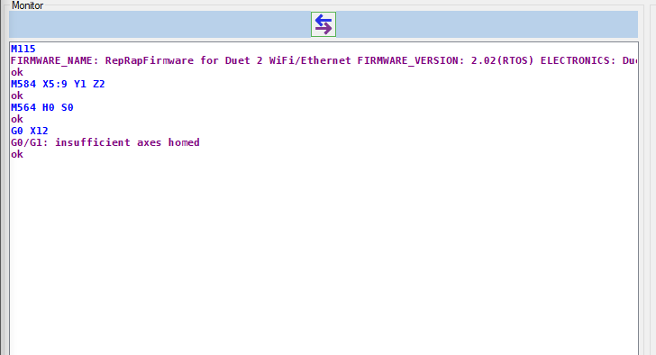
    0_1555327740276_329266a6-0a31-4c0a-bef1-f20c314a4fa0-image.png

    Best regards
    Andreas

    1 Reply Last reply Reply Quote 0
    • undefined
      whosrdaddy
      last edited by whosrdaddy 15 Apr 2019, 11:39

      try relative moves with G91

      1 Reply Last reply Reply Quote 0
      • undefined
        DocTrucker
        last edited by DocTrucker 15 Apr 2019, 11:42

        For homing routines you need to add S2 in any G0 / G1 commands that moves an axis before it is homed.

        For testing move the head/platform to some where where it can move in all directions then tell the machine it is at a specific location such as (10,10,10) with G92:

        G92 X10 Y10 Z10

        This will let you move the axis (go small distances and slow to start) before you are ready to launch into setting up and testing homing routines.

        Running 3 P3Steel with Duet 2. Duet 3 on the shelf looking for a suitable machine. One first generation Duet in a Logo/Turtle style robot!

        1 Reply Last reply Reply Quote 1
        • undefined
          DocTrucker
          last edited by DocTrucker 15 Apr 2019, 11:45

          You could quite easily bench test the electronics with the limit switches and probes loose if you wished. Get direction sorted then write a rough homing routine and prod the switches at appropriate times to give you some confidence in the macros. To be fair though it's not that bad on the machine if you take it easy.

          Running 3 P3Steel with Duet 2. Duet 3 on the shelf looking for a suitable machine. One first generation Duet in a Logo/Turtle style robot!

          1 Reply Last reply Reply Quote 0
          • undefined
            Eplov
            last edited by 15 Apr 2019, 11:55

            Hi Everyone

            Thank you for the answers. This is the setup i am using at the moment. The printer is designed but not build at the moment.

            0_1555329134799_IMG-2099.JPG

            Using the G0 Xnnn S2 code, the warning disappears as it should, but the stepper motor is not moving still. I have the driver hooked up the the breakout board on port E2, number 5. I then use the M584 X5 to set the x-direction to this port.
            With this and the S2 addition to G0 i would expect the motor to start turning.

            1 Reply Last reply Reply Quote 0
            • undefined
              dc42 administrators
              last edited by 15 Apr 2019, 11:55

              To test stepper motor individually, send G91 to select relative mode, then use G1 S2 moves.

              Duet WiFi hardware designer and firmware engineer
              Please do not ask me for Duet support via PM or email, use the forum
              http://www.escher3d.com, https://miscsolutions.wordpress.com

              1 Reply Last reply Reply Quote 0
              • undefined
                DocTrucker
                last edited by DocTrucker 15 Apr 2019, 12:04

                I'm not expecting to be any help but others will need to see the motors section of your config file including acceleration, instantaneous speed, direction, max speed, steps per mm and the feed rate that you have been trying to use.

                Running 3 P3Steel with Duet 2. Duet 3 on the shelf looking for a suitable machine. One first generation Duet in a Logo/Turtle style robot!

                1 Reply Last reply Reply Quote 0
                • undefined
                  Eplov
                  last edited by 15 Apr 2019, 12:20

                  This might be a really stupid question. I have the board hooked up to my laptop now, and the stepper driver directly to the wall, but does the board need more power than what my laptop can provide to send the signal?

                  undefined 1 Reply Last reply 15 Apr 2019, 12:38 Reply Quote 0
                  • undefined
                    whosrdaddy @Eplov
                    last edited by whosrdaddy 15 Apr 2019, 12:38

                    @eplov : you need to supply VIN voltage to drive the onboard stepper motor drivers, not sure about external drivers though...

                    undefined 1 Reply Last reply 15 Apr 2019, 12:44 Reply Quote 0
                    • undefined
                      Eplov @whosrdaddy
                      last edited by 15 Apr 2019, 12:44

                      @whosrdaddy Yeah that makes sense in my head too. If i need to run stepper motors of the build in drivers then i would need extra voltage, but given that the stepper driver is hooked directly up to the wall, and the board only has to output a digital signal i do not know if i needs more voltage.

                      1 Reply Last reply Reply Quote 0
                      • undefined
                        dc42 administrators
                        last edited by 15 Apr 2019, 12:58

                        It sounds that you are using an external stepper driver. How have you connected it to the Duet?

                        Duet WiFi hardware designer and firmware engineer
                        Please do not ask me for Duet support via PM or email, use the forum
                        http://www.escher3d.com, https://miscsolutions.wordpress.com

                        undefined 1 Reply Last reply 23 Apr 2019, 08:14 Reply Quote 0
                        • undefined
                          Eplov @dc42
                          last edited by 23 Apr 2019, 08:14

                          @dc42 I am using a FuyuMotion FMDT220A48NOM Stepper driver and a Nema 34 stepper motor.
                          I have connected the S+ to 5PU+, S- to 5PU-, D+ to 5DR+ and D- to DR-.

                          You can see the circuit diagram for their motion controller and the stepper controller below.

                          0_1556007232021_Circuit diagram.png

                          1 Reply Last reply Reply Quote 0
                          • undefined
                            dc42 administrators
                            last edited by dc42 23 Apr 2019, 09:48

                            Please post your config,g file. I suspect that either you haven't mapped XYZ to your external drivers using M584, or you haven't extended the step pulse timing using M569.

                            It sounds to me that your drivers have a motor disable input instewade of a motor enable input. In which case, you can connect them to the EN+/EN- outputs on the breakout board, but you need to invert the enable polarity in the M569 commands.

                            Duet WiFi hardware designer and firmware engineer
                            Please do not ask me for Duet support via PM or email, use the forum
                            http://www.escher3d.com, https://miscsolutions.wordpress.com

                            undefined 2 Replies Last reply 23 Apr 2019, 11:18 Reply Quote 0
                            • undefined
                              Eplov @dc42
                              last edited by 23 Apr 2019, 11:18

                              @dc42 I am currently only using M584 to set the X axis to port 5 to 9 to test all ports on the breakout board. I have currently not attached the Enable pins, given the same thought as you mentioned.

                              1 Reply Last reply Reply Quote 0
                              • undefined
                                Eplov @dc42
                                last edited by 23 Apr 2019, 11:24

                                @dc42 Everything is working now. It was the enable signal. Thank you very much for your help.

                                1 Reply Last reply Reply Quote 0
                                • First post
                                  Last post
                                Unless otherwise noted, all forum content is licensed under CC-BY-SA