400W Heated Bed.
-
Thank you both for your answers.
Would doing what @bearer suggests (M303 I presume rather than M203), actually warrants that the drawn current will stay within calculated max, set by the P parameter, or full current will be drawn at the start of the heating up?
Otherwise I will just lower the voltage, yeah
")
Thank you!
-
@nuverian said in 400W Heated Bed.:
Thank you both for your answers.
Would doing what @bearer suggests (M303 I presume rather than M203), actually warrants that the drawn current will stay within calculated max, set by the P parameter, or full current will be drawn at the start of the heating up?
Otherwise I will just lower the voltage, yeah
Thank you!
P0.88 would change the average current to 16.5 * 0.88A = 14.52A. But the RMS current (which is what the fuse cares about) would be sqrt(16.5^2 * 0.88) = 15.48A. So still a little more than the fuse rating - but as I wrote before, that is unlikely to matter.
Or you could replace the fuse by a 20A one. If you get a direct heater short circuit, the PSU's short circuit protection is likely to cut in before the fuse blows.
-
@dc42 Thank you for the extra information.
-
Depending on the material the heater is made from the resistance could change a small but still significant amount as the temperature increase, so the current will decrease as the temperature increase.
You can easily just heat up the bed, disconnect it and repeat the resistance measurement while still hot, you may find the peak current is only over the fuse rating for a brief period of time, in which case you may not have to do anything at all unless operating at a unusually high ambient temperature.
-
@bearer said in 400W Heated Bed.:
Depending on the material the heater is made from the resistance could change a small but still significant amount as the temperature increase, so the current will decrease as the temperature increase.
That effect is very significant for PCB heaters, because copper has a large temperature coefficient of resistance. Silicone heaters normally use nichrome wire, which has a much lower temperature coefficient of resistance, so the effect is usually negligible.
Many years ago I tried to convert a basic soldering iron to a temperature-controlled on by measuring the change in the resistance of the element. It worked after a fashion, but the element was wound using nichrome wire, so I was unable to get a sufficiently accurate measurement.
-
Yeah, recalled this from the ridiculously underdimensioned PCB heater in the Up Mini.
But given silicone heaters can be both nichrome wire or copper on kapton foil ala flexible PCBs I figured it'd be easier to just repeat the measurement than to try and identify the heater.
-
Thank you both for extra information and help.
I decreased the power supply voltage for now, but I will order an SSR to do the switching, since I am losing about 100W bed heating power (down to 300W from 400W now). It's a DC 300x300mm PCB bed by the way.
I wouln't want to change the fuse to a 20A since 18A is the Duet rated max (better safe than sorry).
Thanks again
-
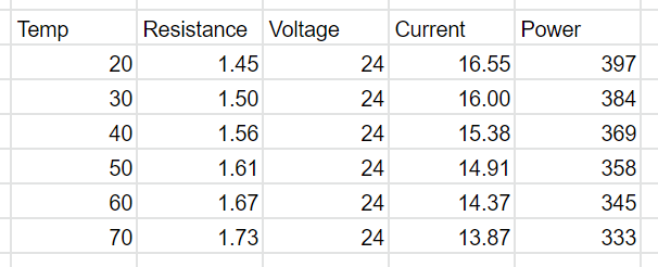
Given its a PCB heater, it'll definitively be copper. And pr your measurement its 1.45ohm at room temperature (which I presume is 20C). That means already at 50C it will be below 15A because the resistance has increased to 1.61ohm, but I understand your desire to play it safe.
-
Thanks @bearer .
I will do your suggested test (heat -> measure -> heat -> measure) tomorrow and let you know what resistance measurements I came up with -
Curious to see how it fits the theory!
-
@bearer
So, I did the test and that confirms it
I incrementaly heated up the bed at target temp each time, unplug and measure it. Done at 21v although I don't think that matters much for this.- 28C - 1.45 (my room temp)
- 40C - 1.53
- 50C - 1.63
- 60C - 1.65
- 70C - 1.72
- 80C - 1.72
It is interesting to see that at about 50-60 C the resistance does not change much. Also at least in my test, the resistance stayed the same at 70C - 80C, so I presume that about 70C the max change has been reached.
Thanks a lot for I learned something new!
-
@nuverian said in 400W Heated Bed.:
Done at 21v although I don't think that matters much for this.
Yeah, voltage would only affect the current and power, and the time it took. Resistance is purely a factor of the temperature.