JoergS5 parallel five bar scara
-
I built this little toy to play with a more agile arm. The only things that collides are the proximal arms. It happily does all work modes. With very poor precision
")
I wish I had more duets, or some other lesser board that could run RRF. The little 8-bit arduino chokes up fast. It's like being back in the 80's, but with better tools.

-
@bondus your image reminds me of my first model to understand parallel scara. I built it from wood. Playing around with it really helped understanding the idea.
If you want to try alternative electronics, you can try Cortex M7 based boards. The disadvantage is of course that all other things like stepper drivers are missing, compared to Duet.
-
Some of the academics have strange ideas. Found this oddity in an (unpublished) paper:

I need to sign up to the university again to get access to all the pay-walled academic papers. -
I finally started working on a calibration method again, my arm produced horribly twisted prints. It works now.
I did something similar to how klipper does delta calibration. You print a model, measure a lot of distances and feed that into a program that figures out what arm lengths (4 of them) and homing angles you have.
It's doing a pretty brutal search looking for a solution with the least sum of square of errors.
It took a few models and measuring methods to get it working. Too few or not properly selected measurements made it find strange solution, the resulting printed models where right but other prints were twisted.
I could probably steal the model and method used by klipper delta calibration. It looks like they have a clever method to make it ignore the errors introduced by printed walls being slightly too big or small.
I'm not sure what to do with the code. I could port it to javascript and integrate it into the little tool I made before.
This calibration tool is pretty necessary if you build the printer with printed parts and hand tools, it's hard to get things exact and it's hard to measure the built printer.
Before calibration to the left: P161.40:161.40 D207.00:206.00 B227.00:151.50
After calibration to the right: P161.18:162.43 D208.28:209.97 B227.84:152.16

I did some experiments with crazy print speeds and accelerations. Printing at 300mm/s and 12000mm/s/s acceleration works fine mechanically. The extruder complains and the ghosting is horrible, but the arm keeps up fine
https://www.youtube.com/watch?v=MW8HApFoy38
It's quite fascinating running with very high acceleration. I wish my machine was stiffer. -
@bondus You have a nice printer and good speed.
I am still gathering ideas about two main aspects building the printer:
- how to make stiff arms and hinges without backlash. Using a gear 1:30 without backlash between stepper and arm
- diy an optical encoder to define the exact end stops
I know what you mean with your comment about university. I tried to get access to researchgate, but without success. They only accept if you're a student or have written a scientific article. I tried it two times. Fortunately some articles are open access.
-
There is an interesting article: Dissertation "Neuartige Drehgelenke für reibungsarme Mechanismen – Auslegungskriterien und Berechnungsmethoden" von Kern 2013, discussing about backlash free hinges. This should allow a higher precision of the arms.
-
@joergs5 said in JoergS5 parallel five bar scara:
how to make stiff arms and hinges without backlash.
My very naive implementation with preloaded thrust bearing works amazingly good for the elbows. It is definitely not the right way of doing it and I expect the bearings to break pretty fast.
I got some fancy angular contact bearings on aliexpress, very nice ABEC-5 bearings, just $5 a piece. DexTAR use two of those in each elbow, preloaded, as they are supposed to be used. But my prototype with those bearings and printed parts does not work very well. PLA is too soft.You are right chasing backlash! A small backlash or flex is amplified further out.
Don't forget to make the tower the arms are attached to as stiff as possible. My tower is a bit soft with 3 12 mm rods and a single 3060 extrusion to the top. It's hard to find space for the tower if you want good mobility for the arms. Reprap morgan has an interesting arrangement of the pipes in it's tower, triangulation is good.
"Neuartige Drehgelenke". Interesting, bushings and flexible joints. I have to dust off my German and have a closer look...
-
@joergs5 said in JoergS5 parallel five bar scara:
diy an optical encoder to define the exact end stops
Double sided tape and a piece of bent metal. That's why I need calibration
")

-
The calibration is not perfect.
Small configuration errors gets amplified when you get close to singularities. The bent line at the top are ~50mm from where the distal arms are at 180°.

I need a bigger bed
-
@bondus The optical encoder I'm working on is:
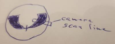
I will use an ESP32-CAM for every stepper, let it communication through I2C with Duet (ESP32 in slave mode). The image shows a printout on transparent film. It is mounted on the big round geared part. The camera knows the position: lot of black means high angle, lower means approaching endstop position (left and right in different colors, not shown here). At endstop I will try to find a fine tuned pattern. The ESP32-CAM camera is an OV2640 with 2.2 micrometer pixel size, so exact enough. This construction has the benefit of knowing where the stepper is and approaching the endstops from both sides.
-
@JoergS5, the stuff I pushed to my repo yesterday does not work properly for v3. The obvious changes were easy to do but there are some issues with homing.
I home both arms at the same time using:
G91 ; relative positioning
G1 S1 X300 Y300 F900 ; move quickly to endstop and stop there (first pass)
G1 S2 X-4 Y-4 F900 ; go back a few mm
G1 S1 X300 Y300 F90 ; move slowly to endstop once more (second pass)
G90 ; absolute positioningBut now it stops when one endstop is hit and leaves one axis not-homed, it did not so that before. That behaviour should be controlled by QueryTerminateHomingMove(). I'll dig around and solve it...
By homing both arms at the same time you avoid ending up in impossible positions. Like linear deltas.
-
@bondus Thank you for the warning and details. I will home both arms at the same time to avoid coming into a singularity area. I'll show you the implementation.
-
@JoergS5, I tested how the angle limitations in the firmware works in reality: The arms happily moves into all kind of not allowed angles; it does not work
It does not totally bug out and sends the steppers to impossible positions that it used to do before, but it totally ignores the limits.It looks like RRF relies on LimitPosition(), which is not properly implemented. IsReachable(), that is properly implemented is not used much.
LimitPosition() is easy to implement if the config option Z used. Could that not use the normal m208 configuration?
But if that is not in use we have to rely on the angle limitations to from a given coordinate compute a new coordinate that is within the angle limits. This seems to be quite complicated, and each work mode is different. It's doable though.
We could skip implementing the complicated LimitPosition() if we rely on using a square, or circular, limit area, and rely on that the user has set a reasonable area. The lazy solution
I have a homing position that is at the extreme angles of both arms, the position the head has at those angle will most certainly be outside a reasonable print area (it likes to fight with my desk lamp). For that to work it must be possible to do a move from outside any limits defined by coordinates to inside the limited area.
Your optical encoder would help since you can have a homing position at a reasonable coordinate. I simplified version that just tells if its left of, right of or on the homing position would also make homing easier.
-
@bondus I propose we search the reason. I must confess I did not fully understand the limit methods, I copied them from the Scara code. I hope you can live with the errors by limiting your print area. I will try to find the reason later, after I finish the build.
The encoder will be built with three ESP32-CAM (I will use the Z endstop with it also) and one STM32F7 board which communicates to Duet. I will encode the encoder printout with a binary pattern, such that + and - degree can be directly read. Something like the attached image, but rounded around the middle point.
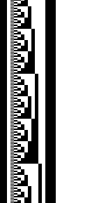 The black bars left and right mark the ends, in the middle the first bit is + or -, the other bits calculate to the degree.
 -
@JoergS5, a binary encoded position encoder.
I wonder how you will make use of that with the Duet/RRF? What signals do you plan to send to the board? Conditional gcode would make it useful in a homing script.
-
@bondus Duet shall send a M260 over I2C to the ESP32 or STM32 board, the external board will set the steppers to the endstops, then sending ok back when finished. I am not sure how the external board moves the steppers (could be some crude rr_ commands, but should be easier).
-
@bondus I will try the Smuff way serial connection https://github.com/technik-gegg/SMuFF-Ifc to send and receive data.
The optical encoder is developing, if calculated correctly, 1/10 degree or a bit better is achievable (encoding with gray code: https://en.wikipedia.org/wiki/Gray_code ). -
In case someone wants to follow my optical encoder procedure: I've created a github repository here: https://github.com/JoergS5/OpticalEncoder with a first png gray code for printout and the java program to create it.
-
@JoergS5, you are remaking a classic old rotational encoder with gray coding.
With a powerful CPU and a high resolution linear sensor it must be possible to create a better pattern. Using a clever pattern, some image processing, error correction, viterbi, e.t.c. it must be possible to get far better resolution. The mechanical industry have a lot of old tech that needs to be renewed.To be useful in our case a 1/10 deg resolution of the arms is not good enough for positioning.
-
@joergs5. Do you have any datasheets on those linear sensors? It's quite an interesting problem