DUET 2 WiFi FSR no workie - config?
-
My FSR trinket isn't talking to the DUET2 WiFi.
JohnSL board and FSRs all signal properly;using my finger lightly on the build plate the trinket red LEDs light up correctly/individually/averaged depending on pressure location.
Should I see anything blinking on the DUET board, or see the Z-probe GUI change?
Z-probe GUI always reads 0Wiring to the Z-probe connector is correct according to DUET Z-probe wiring diagram.
Using the OEM GreenBlackRed assignments for the JohnSL
FSR board is wired to Duet z-probe as:
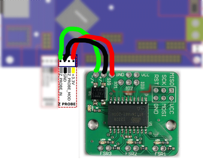

I've tried running g30 and tapping the deck, and switching the wiring between GND and IN. Red wire has remained 3.3v(?)
The JohnSL trinket lights up as it should, hotspots/averaged, but that signal doesn't halt the g30 as it should so I shut the thing down and try again.
Ran g32
effector tracked down to bed,
moved to Z periphery,
slowly lowered to trigger FSR - FSR showed contact(lit up)
crashed build plate until I emergency aborted(but not before the effector was tweaking arms and effector plate joints ...)
FSRs just aren't talking to DUET.
nothing registers in GUI; shouldn't I be seeing a response here(Z-probe) when manually/other triggering the FSRs?: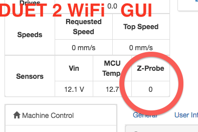
Not sure what else to do
latest config: (FSR@bottom)\\\
M550 PODWOOD_CLAY_01 ; Printer name
M555 P2 ; Gcode Output Type
M552 S1 ; Enable Wifi
G21 ; Work in millimeters
G90 ; Send absolute coordinatesM569 P0 S0 ; Drive 0 goes forwards (X)
M569 P1 S0 ; Drive 1 goes forwards (Y)
M569 P2 S0 ; Drive 2 goes forwards (Z)
M569 P3 S0 ; Drive 3 goes forwards (E0)
M569 P4 S0 ; Drive 4 goes forwards (E1)M574 X2 Y2 Z2 S1 ; set endstop configuration (all endstops at high end, active high)
M665 R144 L291.06 B135 H375 X0 Y0 Z0 ; delta radius, diagonal rod length, printable radius and homed height
; Y X Z are tower angle offsets
M666 X0 Y0 Z0 ; endstop offsets in mmM350 X16 Y16 Z16 E16:16 I1 ; Set 16x microstepping w/ Interpolation
M92 X80 Y80 Z80 ; Set axis steps/mm
M92 E400.0:400.0 ; Set extruder steps/mmM906 X1200 Y1200 Z1200 E1200:1200 I50 ; Set motor currents (mA) and idle current %
M201 X4200 Y4200 Z4200 E5000 ; Accelerations (mm/s^2)
M203 X15000 Y15000 Z15000 E15000 ; Maximum speeds (mm/min)
M566 X2000 Y2000 Z2000 E2000 ; Maximum instant speed changes mm/minuteM106 P0 H-1 ; PART-DRYING FAN
M106 P1 S1 H-1 ; DUET CPU fan
M106 P2 T25 S100 ; LDM fanM563 P0 D0 S"LDM_01" ; create a named tool using extruder drive 0
M558 P5 X0 Y0 Z0 H15 F200 I1 ; FSR Settings
G31 P500 X0 Y0 Z-0.3 ; Probe trigger value and offsets
M270 I1 P1 S0.05 ; Enabled Probe doubletap w/ 0.05mm tolerance
M557 R140 S30 ; default bed mapping
M501 ; Load saved config values
T0 ; Select Tool 0M302 ; Report current state
M302 P0 ; Allow cold extrusion
M375 ; Load height map\\\\
I'm thinking there's some config like M581: Configure external trigger or M585: Probe Tool (?) that I need to mess with to have the Z-probe get initialized?
What does this do?
M270 I1 P1 S0.05 ; Enabled Probe doubletap w/ 0.05mm tolerance -
This post is deleted! -
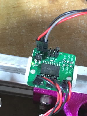
SOLVED

That is, on a Rostock Delta Max V3 running JohnSl FSR kit
-
Strange, your first photo looked correct to me.
-
Yes, the wiring diagrams I saw clearly are the first layout.
Then I found one that had some color-blindness going on,
but got me there:It states:
Grey is the Signal, red is 3v3 and black is ground
(this is not my board/trinket)
I was convinced 'gray'(my red) is 3.3v, because the board was getting power and working/sensing/lighting up the correct LEDs.
Right?
I just stared at my config and thought,"what could possibly go wrong? I might fry a $7 (USD) part, but ...
MAGIC COULD HAPPEN"
I mean,
SCIENCE COULD HAPPEN!


and there was much rejoicing
-
Nurbie , I'm having similar problems .
Your solved photo shows the connections at the duet end.What are your connections at the FSR end ?
Is red wire connected to signal on fsr board and at Duet end to Z Probe In ?
My confusion stems from this paragraph in the duet dozuki:
If using JohnSL's trinket board: Connect its Vcc, Output and Ground pins to 3.3V, IN and GND on the Z-probe connector respectively and select mode 5.
John's board does not have Vcc , Output or Ground labels on the 3 pins in the corner of the board.
They are labelled: Signal , -/+ , +/-